
HYDRAULIC IRONWORKER
PUNCHING, SHEARING & NOTCHING FOR METAL FABRICATION
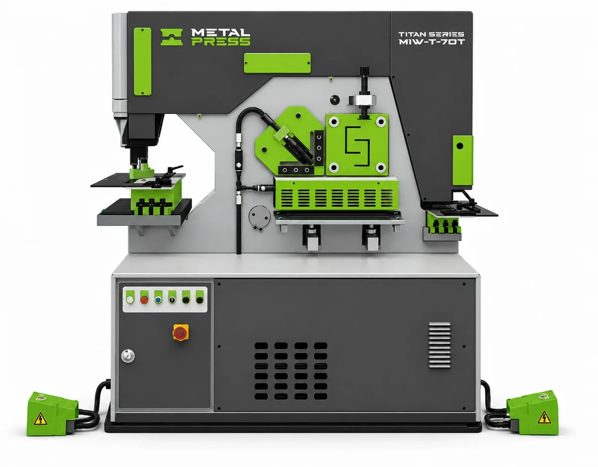
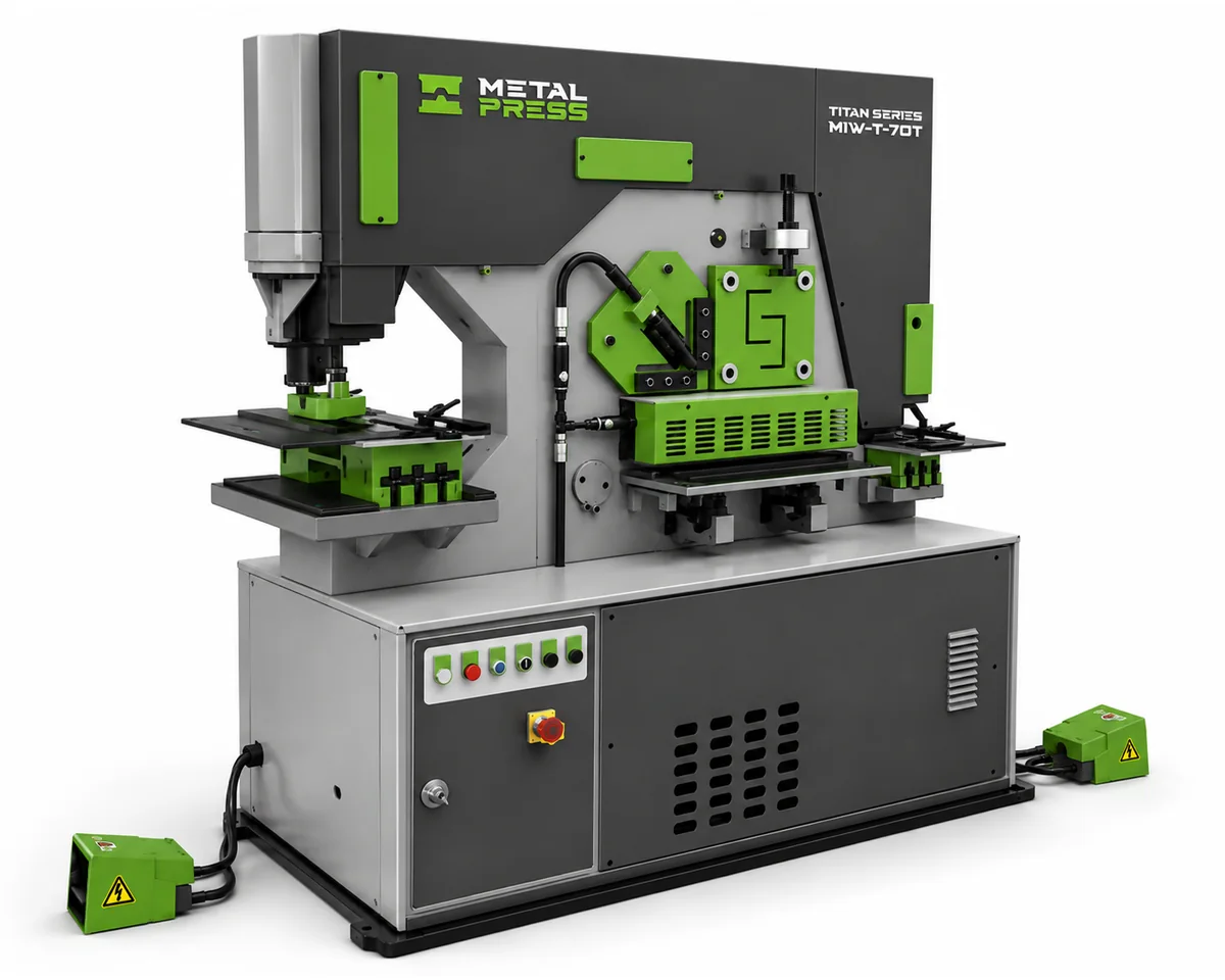
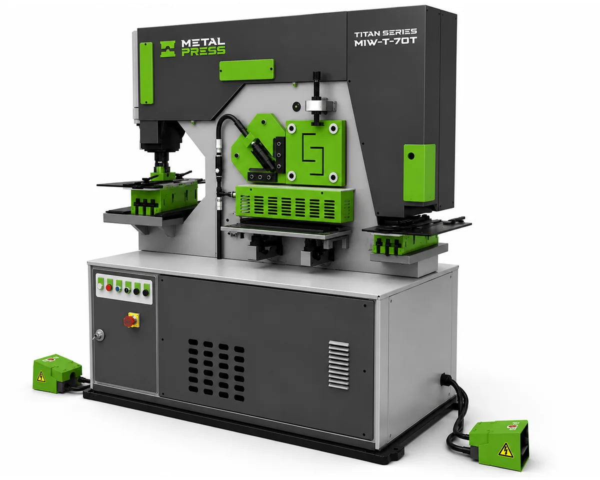
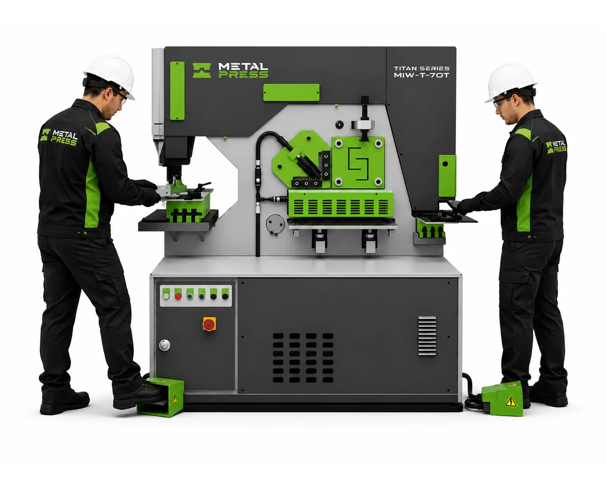
HYDRAULIC IRONWORKER
One machine. Dual operator. Endless capability.
The fabricator's workhorse.
- Five core workstations in one compact platform
- Dual-operator design
- Six models: MIW-T-70 through MIW-T-275
- 70–275 US ton punching pressure range
- Punching, flat bar, bar and angle shearing
- Dedicated notching station
- Quick-change punch nut and adjustable work tables
- Optional bending and structural tooling
- Custom punches, dies and special profiles
- Punches and dies sold separately
GET A QUICK IRONWORKER QUOTE
Send us your materials, part sizes and required operations. We'll help match the machine and tooling to your work.
HELP US SIZE THE RIGHT IRONWORKER
For the fastest recommendation, include:
Material type and grade
Mild steel, stainless steel, aluminium or other material, with strength if known.
Maximum thickness and section sizes
Plate width, round or square bar size, and angle or channel dimensions.
Hole and notch dimensions
Hole diameter, shape, spacing and notch geometry.
Required operations and tooling
Punching, shearing, notching, optional bending or custom work.
Part drawings and production volume
Include drawings and expected quantities when available.
Not sure of every specification?
Send the details you have. Our team can help review the required station capacities and tooling.
SIX TITAN CLASS MODELS
Compare punching pressure, throat depth and station capacities to find the MIW-T model that fits your fabrication requirements.
MIW-T-70
70 US tons / 63.5 tonnes
11.81 in / 300 mm throat depth
5 HP motor
MIW-T-100
100 US tons / 90.7 tonnes
13.98 in / 355 mm throat depth
7.5 HP motor
MIW-T-130
120 US tons / 108.9 tonnes
15.75 in / 400 mm throat depth
10 HP motor
MIW-T-175
175 US tons / 158.8 tonnes
23.62 in / 600 mm throat depth
15 HP motor
MIW-T-220
220 US tons / 199.6 tonnes
23.62 in / 600 mm throat depth
20 HP motor
MIW-T-275
275 US tons / 249.5 tonnes
23.62 in / 600 mm throat depth
25 HP motor
FIVE WORKSTATIONS. ONE MACHINE.
A compact platform for everyday fabrication.
The Titan Class MIW-T combines punching, flat bar shearing, bar shearing, angle shearing and notching in one dual-operator machine. Move between core fabrication tasks with dedicated workstations and application-specific tooling.
Optional attachments extend the platform to selected pipe, structural and bending operations. Configure the equipment around the parts you make.
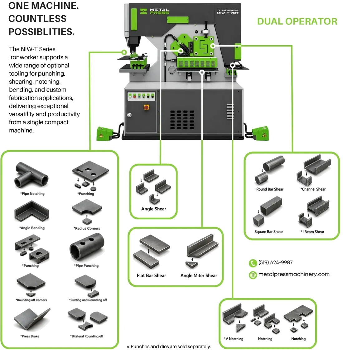
TECHNICAL OVERVIEW OF THE MIW-T IRONWORKER
Punch, shear flat bar, cut round and square bar, shear angle and notch material on a single compact machine.
The MIW-T uses a dual-operator layout. Select the machine and workstation arrangement around your intended production tasks.
The main slide uses precise vertical motion for punching and optional forming applications. Adjustable short-stroke limit switches support repetitive work.
Every station has its own dimensional capacity. Check material strength, thickness, section size and required tooling together. Punches and dies are sold separately, and optional attachments must be specified.
STANDARD FEATURES
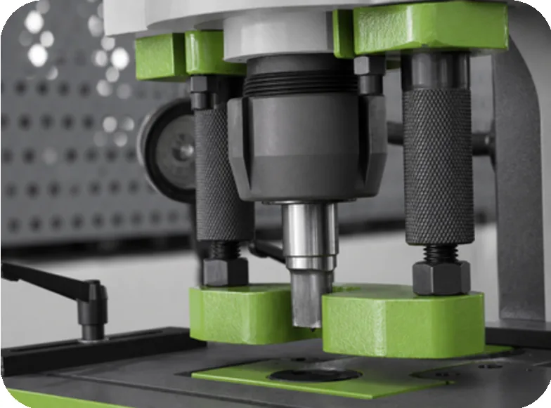
PUNCHING STATION
Quick changes. Clear visibility. Flexible positioning.
The MIW-T punching station combines a quick-change punch nut with a high-visibility stripper and a large, two-piece work table. Integrated scales and stops help position work consistently.
- Interchangeable stripper plates help reduce material deformation.
- The standard dual-opening die block accommodates round punch dies up to 2 in (50 mm).
- Punching capacity depends on the selected model, hole size, material and thickness.
Punches and dies are sold separately. The 2 in die accommodation is not a full-thickness punching capacity rating; see the specification table.
FLAT BAR SHEARING
Clean cuts with adjustable support and guidance.
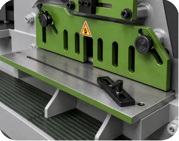
The flat bar shear uses a precision-machined upper blade and a reversible lower blade with four usable cutting edges. The support table and guides help position material for straight and angle miter cuts.
- Easy-to-adjust hold-down for different material thicknesses.
- Adjustable angle miter cutting.
- Model-specific width and thickness capacities.
Compare both plate width and thickness in the station capacity table when selecting a machine.
ROUND & SQUARE BAR SHEARING
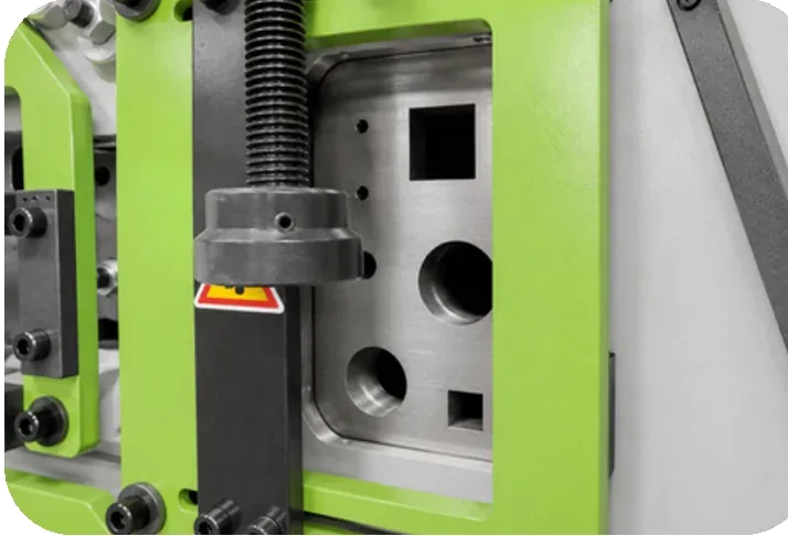
One adjustable hold-down for a range of bar sizes.
The bar shearing station cuts round and square stock with a single adjustable hold-down. Six models offer different bar capacities, from compact general fabrication through larger structural work.
Maximum round bar diameters range from 1-3/4 to 3-1/8 in. Maximum square bar sizes range from 1-9/16 to 2-9/16 in, depending on the model and material rating.
ANGLE SHEARING
Single-cut shearing with virtually no material loss.
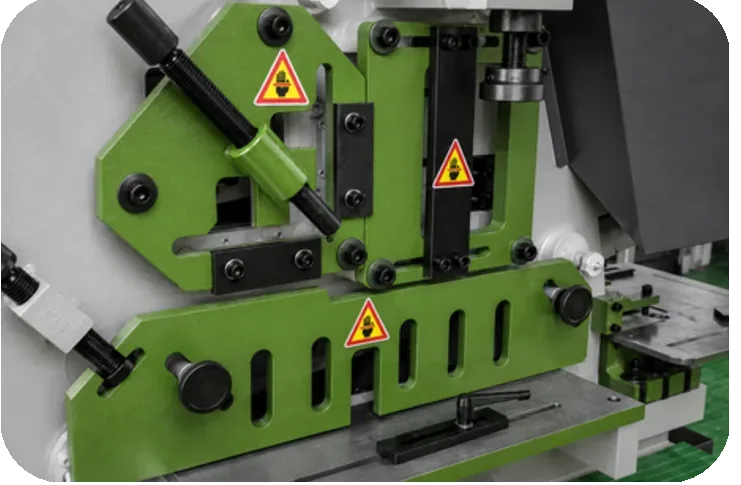
The angle station produces a clean single-cut shear and supports 45° miter cutting. Stationary blades provide four usable cutting edges.
- Selectable corner radii for small and large angle sections.
- Dedicated 90° and 45° capacities for each model.
- Integrated support for repeat positioning.
Use the angle capacity rows to compare leg dimensions and thickness together.
NOTCHING STATION
Notch flat bar, angle and structural material.
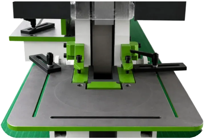
The notching station includes an electrically interlocked safety guard and an integrated gauging table with adjustable stops.
Positioning stops support repeated notch locations across flat bar, angle and suitable structural sections. Maximum notch width, depth and material thickness vary by model.
SHORT-STROKE ADJUSTMENT
Set the travel needed for repeat work.
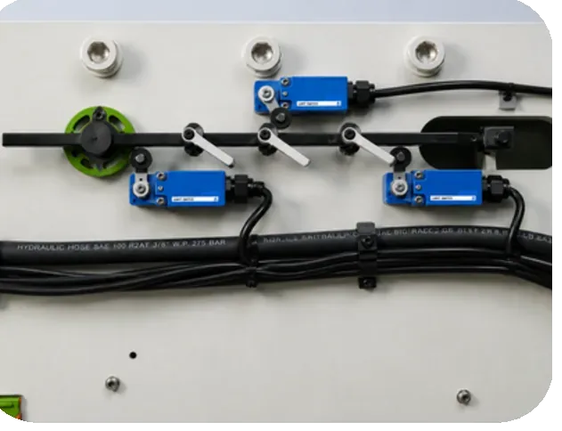
Three adjustable limit switches allow short-stroke settings. Reducing unnecessary travel can shorten the operating cycle for repetitive work.
Compare the strokes-per-minute rating for each model in the specifications below. Actual production output depends on the operation, part handling and setup.
LED WORK LIGHT
Position lighting where the job needs it.
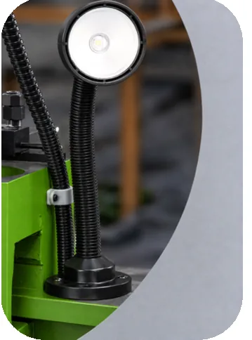
A magnetic-base LED work light improves visibility at the work area. The movable base helps place light around the tooling and material being processed.
Clear visibility supports setup and positioning across the ironworker's workstations.
ELECTRIC BACKGAUGE
Repeat cut lengths with a 40 in gauge.
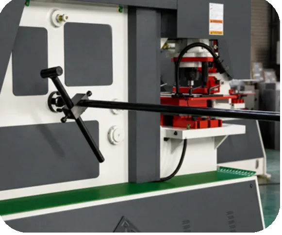
A 40 in (1000 mm) electric backgauge supports repetitive cutting, with an extension available for longer parts.
OPTIONAL EQUIPMENT & TOOLING
An optional rear retaining position device is also shown. Confirm the backgauge, extension and retaining-device arrangement for the selected model and application.
PUNCHES, DIES & HOLDERS
Configure the punching station around your parts.
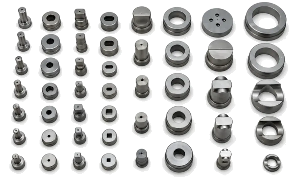
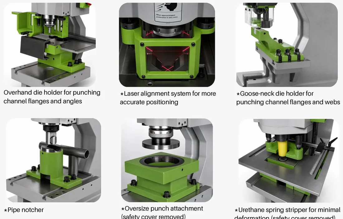
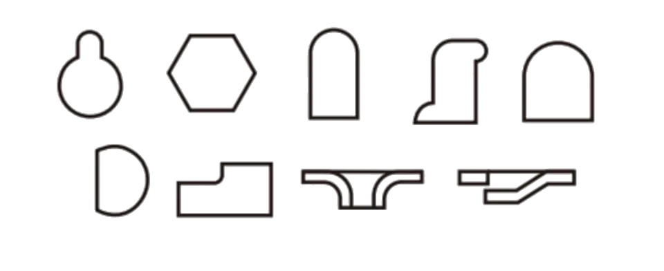
A range of punches and dies supports different hole shapes and fabrication tasks. An overhang die holder provides access to angle and channel flanges, while interchangeable stripper plates support different punching setups.
Select punch size, die clearance and holder geometry to suit the material and profile. Send part drawings with your quote request so the tooling can be matched to the application.
Punches and dies are sold separately.
OPTIONAL PUNCHING EQUIPMENT
Add access, alignment and special applications.
Optional punching equipment expands the work that can be handled at this station:
- Laser alignment device for positioning.
- Goose-neck die holder for channel flanges and webs.
- Pipe notcher and oversized punching equipment.
- Hydraulic stripper for demanding applications.
- Urethane spring stripper to help limit material deformation.
Covers have been removed in some photos to show the tooling. Operating guards must remain in place.
HYDRAULIC PLATE HOLD-DOWN
Optional automatic clamping for flat bar and plate.
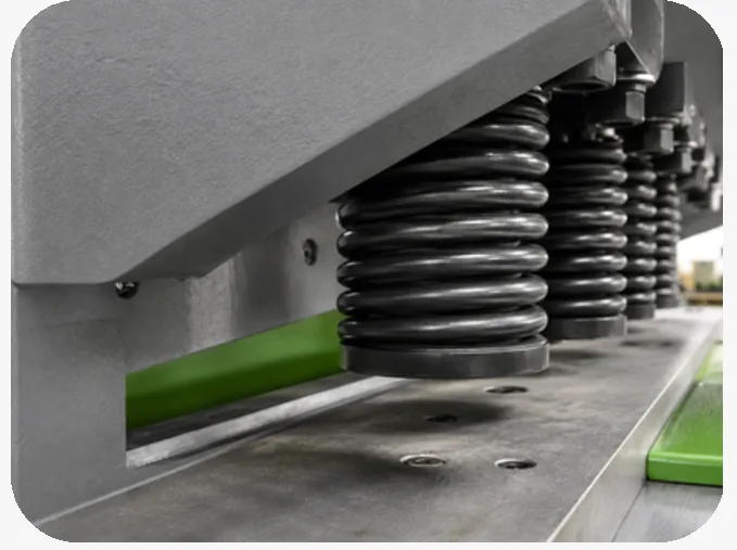
The optional hydraulic hold-down automatically secures the material at the plate shearing station. It supports repeat work where consistent material restraint is important.
Discuss the material range and cutting sequence with MetalPress to determine whether the hydraulic hold-down suits your application.
OPTIONAL STRUCTURAL SHEARING
Tooling for channel and other structural profiles.
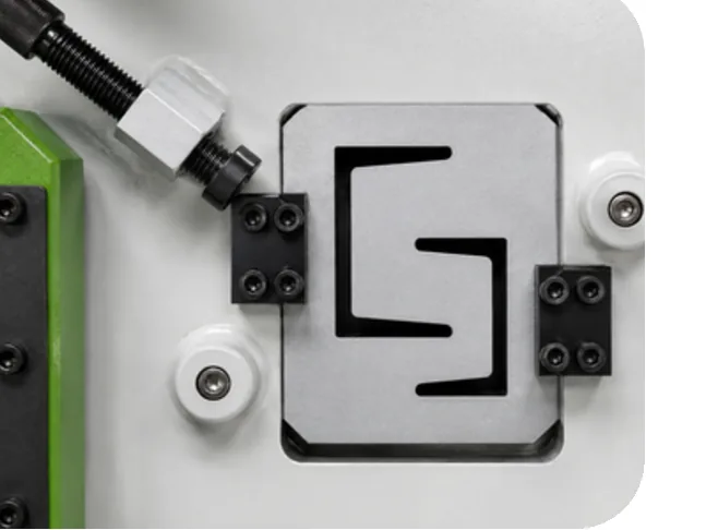
Optional structural tooling allows the ironworker to handle selected channel and other sections. Model-specific I-bar, T-joist and U-channel capacities are listed in the specifications below.
Profile geometry, section thickness and tool availability need to be checked for the chosen model. Supply the section drawing and material grade with your enquiry.
HYDRAULIC ANGLE HOLD-DOWN
Optional restraint at the angle station.
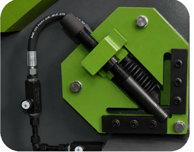
An optional hydraulic hold-down secures angle material during shearing. This option complements the angle station's cutting and miter capabilities.
Confirm the hold-down and tooling configuration against your angle dimensions and production requirements when requesting a quote.
OPTIONAL V-NOTCHING
Additional notch shapes with application-specific tooling.
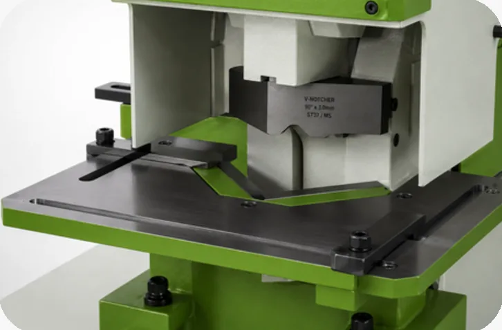
Optional V-notching tooling adds another fabrication operation to the MIW-T platform. A larger V-notching attachment is also available for the punching side.
Compare the V-notch and large V-notch dimensions separately in the specification table. Confirm tool compatibility and the intended material before ordering.
OPTIONAL BENDING & SPECIAL TOOLING
Extend the platform beyond its five core stations.
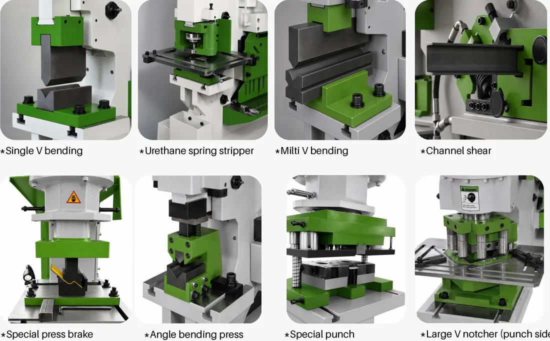
The main slide provides precise vertical motion for punching and optional forming operations. Available optional attachments include:
- Single V and multi V bending tools.
- Special press brake attachment and angle bending press.
- Channel shearing, special punches and a large V-notching tool.
- Urethane spring stripper and application-specific holding equipment.
These attachments are optional. Bending capacity depends on tooling, material and bend width; compare the separate bending rows in the specification table.
CUSTOM TOOLING
Punches, dies and profiles made around your application.
Custom punches, dies and special profiles can be designed and manufactured for unique requirements, from simple holes to complex profiles and formed shapes.
Send drawings, material information, dimensions and expected production volume to MetalPress. Our team can review the tooling approach and machine fit with you.
MIW-T IRONWORKER SPECIFICATIONS
Compare all six models and each workstation's capacity below. Capacities are rated for materials with tensile strength up to 65,000 psi.
Specification note: The MIW-T-130 has a rated punching pressure of 120 US tons. Confirm this rating with MetalPress when specifying the machine.
On smaller screens, scroll the tables horizontally to compare models.
| SPECIFICATIONS – US STANDARD | ||||||
|---|---|---|---|---|---|---|
| Specification | MIW-T-70 | MIW-T-100 | MIW-T-130 | MIW-T-175 | MIW-T-220 | MIW-T-275 |
| Punching pressure (US tons) | 70 | 100 | 120 | 175 | 220 | 275 |
| Maximum steel plate cutting thickness (in) | 1/2 | 3/4 | 1 | 1-1/4 | 1-1/2 | 2 |
| Rated material tensile strength (psi) | ≤65,000 | ≤65,000 | ≤65,000 | ≤65,000 | ≤65,000 | ≤65,000 |
| Shear angle (°) | 7 | 8 | 8 | 8 | 8 | 8 |
| Slider stroke (in) | 3.15 | 3.15 | 3.15 | 3.15 | 3.15 | 3.15 |
| Strokes per minute (SPM) | 9–25 | 12–28 | 12–28 | 12–28 | 10 | 10 |
| Throat depth (in) | 11.81 | 13.98 | 15.75 | 23.62 | 23.62 | 23.62 |
| Motor power (HP) | 5 | 7.5 | 10 | 15 | 20 | 25 |
| Overall dimensions (L × W × H) (in) | 64.6 × 28.7 × 69.7 | 73.2 × 31.5 × 74.8 | 92.3 × 37.8 × 82.3 | 105.5 × 41.0 × 90.6 | 116.9 × 48.8 × 92.5 | 118.1 × 56.7 × 96.5 |
| Machine weight (lb) | 4190 | 5510 | 11464 | 14991 | 24251 | 31967 |
| SPECIFICATIONS – US STANDARD | ||||||
|---|---|---|---|---|---|---|
| Specification | MIW-T-70 | MIW-T-100 | MIW-T-130 | MIW-T-175 | MIW-T-220 | MIW-T-275 |
| Punching | ||||||
| Punching hole (diameter × thickness) (in) | 1 × 5/8 | 1-1/4 × 3/4 | 1-3/8 × 1 | 1-1/2 × 1-1/8 | 1-9/16 × 1-3/8 | 1-9/16 × 1-1/2 |
| Punching table height (in) | 37.8 | 38.2 | 41.9 | 46.1 | 47.8 | 49.0 |
| Flat bar shearing | ||||||
| Plate shear (width × thickness) (in) | 9-7/8 × 5/8 15-3/4 × 5/16 | 13 × 3/4 18-7/8 × 3/8 | 13 × 1 23-5/8 × 5/8 | 13 × 1-1/8 23-5/8 × 3/4 | 15-3/4 × 1-3/8 27-9/16 × 1 | 15-3/4 × 1-1/2 29-1/2 × 1-1/8 |
| Blade length (in) | 16-1/8 | 19-1/8 | 23-13/16 | 23-13/16 | 28 | 29-15/16 |
| Angle steel trimming (in) | 1 × 4-7/8 × 1/2 | 1-3/8 × 5-1/2 × 1/2 | 1-5/8 × 6-1/4 × 9/16 | 1-3/4 × 7-1/8 × 5/8 | 2 × 7-7/8 × 11/16 | 2 × 7-7/8 × 3/4 |
| Plate shear table height (in) | 33.9 | 35.0 | 35.4 | 37.4 | 36.8 | 37.4 |
| Bar shearing | ||||||
| Maximum round bar diameter (in) | 1-3/4 | 2 | 2-3/8 | 2-9/16 | 2-3/4 | 3-1/8 |
| Maximum square bar size (in) | 1-9/16 | 1-3/4 | 2 | 2-3/16 | 2-3/8 | 2-9/16 |
| Angle shearing | ||||||
| 90° angle shear (leg × leg × thickness) (in) | 4-7/8 × 4-7/8 × 1/2 | 5-1/2 × 5-1/2 × 1/2 | 6-1/4 × 6-1/4 × 9/16 | 7-1/8 × 7-1/8 × 5/8 | 7-7/8 × 7-7/8 × 11/16 | 7-7/8 × 7-7/8 × 3/4 |
| 45° angle shear (leg × leg × thickness) (in) | 2 × 2 × 3/16 | 2 × 2 × 3/16 | 2-3/8 × 2-3/8 × 1/4 | 2-3/8 × 2-3/8 × 1/4 | 3-15/16 × 3-15/16 × 3/8 | 4-3/4 × 4-3/4 × 3/8 |
| Angle shear table height (in) | 33.9 | 35.0 | 35.4 | 37.4 | 36.8 | 37.4 |
| Structural sections · optional tooling | ||||||
| I-bar (in) | 4-3/4 × 4-3/4 × 1/2 2-3/8 × 2-3/8 × 5/16 | 5-1/2 × 5-1/2 × 1/2 2-3/4 × 2-3/4 × 3/8 | 6-1/4 × 6-1/4 × 9/16 3-1/8 × 3-1/8 × 3/8 | 7-1/8 × 7-1/8 × 5/8 3-1/8 × 3-1/8 × 3/8 | 7-7/8 × 7-7/8 × 11/16 3-1/8 × 3-1/8 × 3/8 | 7-7/8 × 7-7/8 × 3/4 3-1/8 × 3-1/8 × 3/8 |
| T-joist (in) | 2-3/8 × 2-3/8 × 5/16 | 2-3/4 × 2-3/4 × 3/8 | 3-1/8 × 3-1/8 × 3/8 | 3-1/8 × 3-1/8 × 3/8 | 3-1/8 × 3-1/8 × 3/8 | 3-1/8 × 3-1/8 × 3/8 |
| U-channel (in) | 5 × 2-1/8 × 1/4 | 6-5/16 × 2-3/8 × 1/4 | 8-1/4 × 3 × 3/8 | 11 × 3-3/8 × 7/16 | 11-13/16 × 3-1/2 × 1/2 | 12-5/8 × 3-5/8 × 1/2 |
| Structural section table height (in) | 47.6 | 48.0 | 49.6 | 57.9 | 59.4 | 61.0 |
| Notching | ||||||
| Notch (width × depth × thickness) (in) | 3-15/16 × 2-1/8 × 3/8 | 3-15/16 × 2-1/4 × 1/2 | 3-15/16 × 2-1/4 × 9/16 | 3-15/16 × 2-3/8 × 5/8 | 3-15/16 × 2-3/8 × 3/4 | 7-7/8 × 2-3/8 × 3/4 |
| V-notch (side × side × thickness) · optional (in) | 3-3/4 × 3-3/4 × 3/8 | 3-15/16 × 3-15/16 × 1/2 | 4-1/8 × 4-1/8 × 1/2 | 4-1/8 × 4-1/8 × 5/8 | 4-1/8 × 4-1/8 × 3/4 | 4-1/8 × 4-1/8 × 3/4 |
| Large V-notch (side × thickness) · optional (in) | 5-11/16 × 3/4 | 5-11/16 × 3/8 | 5-11/16 × 1/2 | 5-11/16 × 1/2 | 5-11/16 × 19/32 | 5-11/16 × 3/4 |
| Notching table height (in) | 35.8 | 35.4 | 33.9 | 38.0 | 37.4 | 38.4 |
| Bending · optional tooling | ||||||
| Single V-bending (width × thickness) (in) | 9-7/8 × 19/32 | 9-7/8 × 23/32 | 9-7/8 × 25/32 | 9-7/8 × 25/32 | 9-7/8 × 7/8 | 9-7/8 × 15/16 |
| Multi V-bending (width × thickness) (in) | 19-11/16 × 3/16 | 19-11/16 × 3/16 | 23-5/8 × 3/16 | 27-9/16 × 3/16 | 27-9/16 × 5/16 | 27-9/16 × 5/16 |
| SPECIFICATIONS – METRIC STANDARD | ||||||
|---|---|---|---|---|---|---|
| Specification | MIW-T-70 | MIW-T-100 | MIW-T-130 | MIW-T-175 | MIW-T-220 | MIW-T-275 |
| Punching pressure (tonnes) | 63.5 | 90.7 | 108.9 | 158.8 | 199.6 | 249.5 |
| Maximum steel plate cutting thickness (mm) | 12.7 | 19.0 | 25.4 | 31.8 | 38.1 | 50.8 |
| Rated material tensile strength (MPa) | ≤448.2 | ≤448.2 | ≤448.2 | ≤448.2 | ≤448.2 | ≤448.2 |
| Shear angle (°) | 7 | 8 | 8 | 8 | 8 | 8 |
| Slider stroke (mm) | 80.0 | 80.0 | 80.0 | 80.0 | 80.0 | 80.0 |
| Strokes per minute (SPM) | 9–25 | 12–28 | 12–28 | 12–28 | 10 | 10 |
| Throat depth (mm) | 300.0 | 355.1 | 400.0 | 599.9 | 599.9 | 599.9 |
| Motor power (kW) | 3.73 | 5.59 | 7.46 | 11.19 | 14.91 | 18.64 |
| Overall dimensions (L × W × H) (mm) | 1640.8 × 729.0 × 1770.4 | 1859.3 × 800.1 × 1899.9 | 2344.4 × 960.1 × 2090.4 | 2679.7 × 1041.4 × 2301.2 | 2969.3 × 1239.5 × 2349.5 | 2999.7 × 1440.2 × 2451.1 |
| Machine weight (kg) | 1901 | 2499 | 5200 | 6800 | 11000 | 14500 |
| SPECIFICATIONS – METRIC STANDARD | ||||||
|---|---|---|---|---|---|---|
| Specification | MIW-T-70 | MIW-T-100 | MIW-T-130 | MIW-T-175 | MIW-T-220 | MIW-T-275 |
| Punching | ||||||
| Punching hole (diameter × thickness) (mm) | 25.4 × 15.9 | 31.8 × 19.0 | 34.9 × 25.4 | 38.1 × 28.6 | 39.7 × 34.9 | 39.7 × 38.1 |
| Punching table height (mm) | 960.1 | 970.3 | 1064.3 | 1170.9 | 1214.1 | 1244.6 |
| Flat bar shearing | ||||||
| Plate shear (width × thickness) (mm) | 250.8 × 15.9 400.0 × 7.9 | 330.2 × 19.0 479.4 × 9.5 | 330.2 × 25.4 600.1 × 15.9 | 330.2 × 28.6 600.1 × 19.0 | 400.0 × 34.9 700.1 × 25.4 | 400.0 × 38.1 749.3 × 28.6 |
| Blade length (mm) | 409.6 | 485.8 | 604.8 | 604.8 | 711.2 | 760.4 |
| Angle steel trimming (mm) | 25.4 × 123.8 × 12.7 | 34.9 × 139.7 × 12.7 | 41.3 × 158.8 × 14.3 | 44.4 × 181.0 × 15.9 | 50.8 × 200.0 × 17.5 | 50.8 × 200.0 × 19.0 |
| Plate shear table height (mm) | 861.1 | 889.0 | 899.2 | 950.0 | 934.7 | 950.0 |
| Bar shearing | ||||||
| Maximum round bar diameter (mm) | 44.4 | 50.8 | 60.3 | 65.1 | 69.8 | 79.4 |
| Maximum square bar size (mm) | 39.7 | 44.4 | 50.8 | 55.6 | 60.3 | 65.1 |
| Angle shearing | ||||||
| 90° angle shear (leg × leg × thickness) (mm) | 123.8 × 123.8 × 12.7 | 139.7 × 139.7 × 12.7 | 158.8 × 158.8 × 14.3 | 181.0 × 181.0 × 15.9 | 200.0 × 200.0 × 17.5 | 200.0 × 200.0 × 19.0 |
| 45° angle shear (leg × leg × thickness) (mm) | 50.8 × 50.8 × 4.8 | 50.8 × 50.8 × 4.8 | 60.3 × 60.3 × 6.3 | 60.3 × 60.3 × 6.3 | 100.0 × 100.0 × 9.5 | 120.6 × 120.6 × 9.5 |
| Angle shear table height (mm) | 861.1 | 889.0 | 899.2 | 950.0 | 934.7 | 950.0 |
| Structural sections · optional tooling | ||||||
| I-bar (mm) | 120.6 × 120.6 × 12.7 60.3 × 60.3 × 7.9 | 139.7 × 139.7 × 12.7 69.8 × 69.8 × 9.5 | 158.8 × 158.8 × 14.3 79.4 × 79.4 × 9.5 | 181.0 × 181.0 × 15.9 79.4 × 79.4 × 9.5 | 200.0 × 200.0 × 17.5 79.4 × 79.4 × 9.5 | 200.0 × 200.0 × 19.0 79.4 × 79.4 × 9.5 |
| T-joist (mm) | 60.3 × 60.3 × 7.9 | 69.8 × 69.8 × 9.5 | 79.4 × 79.4 × 9.5 | 79.4 × 79.4 × 9.5 | 79.4 × 79.4 × 9.5 | 79.4 × 79.4 × 9.5 |
| U-channel (mm) | 127.0 × 54.0 × 6.3 | 160.3 × 60.3 × 6.3 | 209.5 × 76.2 × 9.5 | 279.4 × 85.7 × 11.1 | 300.0 × 88.9 × 12.7 | 320.7 × 92.1 × 12.7 |
| Structural section table height (mm) | 1209.0 | 1219.2 | 1259.8 | 1470.7 | 1508.8 | 1549.4 |
| Notching | ||||||
| Notch (width × depth × thickness) (mm) | 100.0 × 54.0 × 9.5 | 100.0 × 57.1 × 12.7 | 100.0 × 57.1 × 14.3 | 100.0 × 60.3 × 15.9 | 100.0 × 60.3 × 19.0 | 200.0 × 60.3 × 19.0 |
| V-notch (side × side × thickness) · optional (mm) | 95.2 × 95.2 × 9.5 | 100.0 × 100.0 × 12.7 | 104.8 × 104.8 × 12.7 | 104.8 × 104.8 × 15.9 | 104.8 × 104.8 × 19.0 | 104.8 × 104.8 × 19.0 |
| Large V-notch (side × thickness) · optional (mm) | 144.5 × 19.0 | 144.5 × 9.5 | 144.5 × 12.7 | 144.5 × 12.7 | 144.5 × 15.1 | 144.5 × 19.0 |
| Notching table height (mm) | 909.3 | 899.2 | 861.1 | 965.2 | 950.0 | 975.4 |
| Bending · optional tooling | ||||||
| Single V-bending (width × thickness) (mm) | 250.8 × 15.1 | 250.8 × 18.3 | 250.8 × 19.8 | 250.8 × 19.8 | 250.8 × 22.2 | 250.8 × 23.8 |
| Multi V-bending (width × thickness) (mm) | 500.1 × 4.8 | 500.1 × 4.8 | 600.1 × 4.8 | 700.1 × 4.8 | 700.1 × 7.9 | 700.1 × 7.9 |
Metric values are approximate conversions of the US specifications.
Punches and dies are sold separately. Optional tooling must be specified. Capacity depends on material and tooling. Specifications are subject to change without notice; confirm the final configuration with MetalPress.
FREQUENTLY ASKED QUESTIONS ABOUT IRONWORKERS
A hydraulic ironworker combines several fabrication operations in one machine. The Titan Class MIW-T provides punching, flat bar shearing, round and square bar shearing, angle shearing, and notching. Optional tooling adds selected bending, pipe, channel and special-profile applications.
Yes. The MIW-T is a dual-operator ironworker. Workstation selection, operating procedures and production setup should be reviewed for your application.
The series includes MIW-T-70, MIW-T-100, MIW-T-130, MIW-T-175, MIW-T-220 and MIW-T-275. Punching pressures range from 70 to 275 US tons; the MIW-T-130 is rated at 120 US tons. Compare each station's capacity rather than selecting by model name alone.
Punches and dies are sold separately. Select the required hole sizes, shapes, die clearances and holders for the materials you will process. MetalPress can review the tooling requirements with your quote request.
The capacity tables are based on material tensile strength up to 65,000 psi. Hole diameter, section size, thickness and tooling all affect the usable capacity. Send the actual material grade and part dimensions for confirmation.
Yes, with optional bending tooling. Optional bending equipment includes single V and multi V bending tools, an angle bending press and a special press brake attachment. These are optional attachments with separate capacity limits.
Optional structural tooling supports suitable sections. The specification tables list I-bar, T-joist and U-channel capacities for each model. Confirm the profile geometry, material and tooling availability with MetalPress.
Include the material grade, maximum thickness, required hole sizes, bar and angle dimensions, workstations you need, drawings and production volume. Note any optional bending, notching, backgauge or custom tooling requirements.
Expert Advice
Ironworker Engineering Fit Notes
Select an ironworker by the work it needs to do. Punching pressure alone does not describe plate width, hole diameter, angle size, throat access or notching geometry. Compare the required part against the capacity of every station you plan to use.
MIW-T capacities are rated for material with tensile strength up to 65,000 psi. Stronger material, different section geometry or special tooling can change the usable capacity. Provide the actual material grade, thickness and drawings so the application can be reviewed.
For repetitive work, include production quantities and gauge requirements. For optional bending, structural shearing or custom punches, define the operation and tool dimensions before finalising the machine configuration.
For dedicated CNC sheet metal bending, explore the MetalPress servo hydraulic CNC press brake. For MIW-T machine and tooling selection, request an ironworker quote.