
Mechanical Presses
Compare C-frame and straight-sided mechanical presses for metal stamping and forming.
Choose a Mechanical Press Machine for Your Tooling
MetalPress offers four mechanical press families: single- and double-crank C-frame presses, plus single- and double-point straight-sided presses. Start with your part, die size, force requirement and production sequence, then compare the frame and slide-support arrangement below.
A conventional mechanical stamping press uses a crank-driven slide motion. Selection requires both the force available at the working position and the energy needed for the operation—not nameplate tonnage alone. Send your drawing and tooling information if the correct family is not yet clear.
Explore the Four Mechanical Press Families
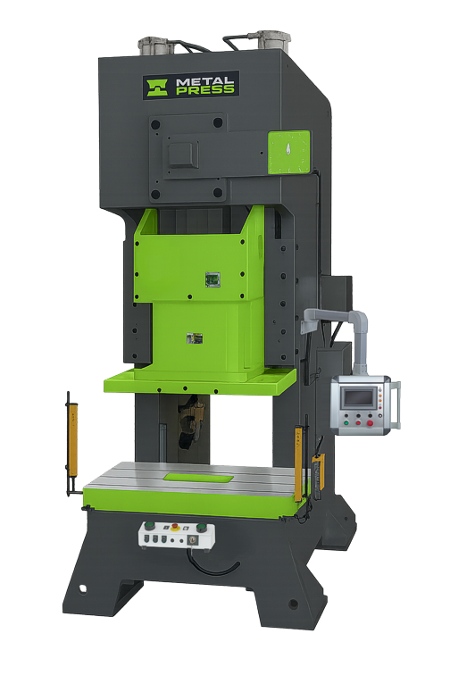
Open-front access for tooling setup and part handling. Compare the die footprint and load location with the selected MSC model.
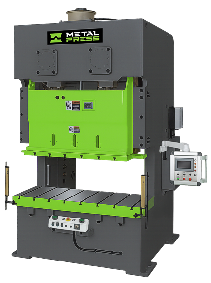
Two-point slide support with a wider tooling layout. Review the actual die envelope and loading balance for an MDC configuration.
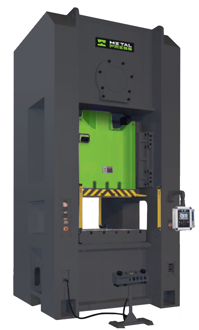
Straight-sided frame with one slide connection point. Match the tooling footprint and central load pattern to the MSE configuration.
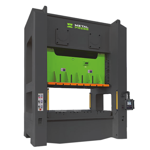
Straight-sided frame with two slide connection points. Review longer tooling, transfer access and load distribution for an MDE configuration.
Compare Frame and Slide-Support Arrangements
Crank count and connection-point count describe the drive/support layout; they are not a substitute for the selected machine’s load limits. Neither two-point support nor a straight-sided frame makes off-center loading unlimited. Verify the tooling load map and the manufacturer’s allowable-load data.
| Family and product | Production fit to evaluate | Key checks before selection |
|---|---|---|
| MSC C-frame single-crank press | Compact dies, blanking, punching and secondary stamping where open access matters. | Check the throat, bolster and slide dimensions, force curve and permissible load position. |
| MDC C-frame double-crank press | Wider dies and parts needing two-point slide support with C-frame access. | Check die length, load balance across both points, feed clearance and off-center load limits. |
| MSE Single-point straight-sided press | Stamping and forming with tooling suited to a single-point straight-sided layout. | Check the working area, load distribution, die height, slide guidance and required energy. |
| MDE Double-point straight-sided press | Longer dies, larger panels and progressive or transfer layouts requiring two-point support. | Check slide and bolster length, load moments, feed/transfer timing and the complete tooling envelope. |
For model ratings, slide and bolster dimensions, and a direct product enquiry, open the relevant MSC single-crank, MDC double-crank, MSE single-point or MDE double-point product page.
How to Specify a Mechanical Press
Define the Operation
Document the material, thickness, blank size, finished geometry, forming depth, tolerance, die type, and required operations.
Calculate Force and Energy
Confirm required tonnage at the working point and verify that flywheel energy is sufficient through the complete production cycle.
Size the Working Area
Match bed, bolster, slide area, shut height, stroke, adjustment, feed height, and die-change access to current and future tooling.
Set the Production Rate
Balance strokes per minute with feeding, lubrication, part transfer, inspection, scrap removal, and safe operator access.
Mechanical Press Applications
Use the metal stamping application guide to describe the operation, the punching and blanking guide for cutting work, and the forming application guide for part geometry and tooling considerations. Selected coining applications also require force and energy review. The process and tooling determine suitability; an industry label alone does not.
If your project calls for a different slide-motion approach, review the servo-mechanical press category. If you are still deciding between drive technologies, use our mechanical-versus-hydraulic selection guide before narrowing the choice to a mechanical model.
Before You Select a Model
Ask for the rated capacity point above bottom dead center, available energy at the proposed speed, allowable off-center loading and reverse loading, stroke, die-height adjustment and tooling-support dimensions. Compare these with the complete die cycle, including feeding, stripping, part removal and scrap handling.
Production rate, accuracy and safeguarding must be agreed for the selected press, tooling and automation package. The category comparison does not establish a guaranteed cycle rate or tolerance.
Request a Mechanical Press Recommendation
Send the material grade and thickness, part drawing, die footprint and weight, required force or trial data, stroke and die height, production target, feed/transfer method, plant utilities and safeguarding requirements. Identify any values that still need engineering development.
Use our press enquiry form for help choosing a family, or the enquiry form on a specific product page if you already have a model in mind.