
IN-PLANT COIL MOVEMENT APPLICATIONS
Plan storage-to-line travel, staging, positioning, and production-equipment handoffs for heavy steel and aluminum coils.
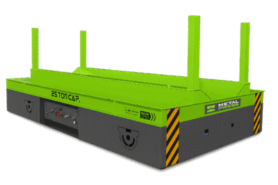
In-Plant Coil Movement and Production-Line Loading
MAP THE ROUTE BEFORE SELECTING THE CART
In-plant coil movement begins with a route map. Document where the coil is received, stored, staged, rotated, inspected, loaded into a slitter or cut-to-length line, presented to a decoiler or uncoiler, and delivered to a press-feeding system. Each handoff should define coil weight, OD, ID, width, eye orientation, center of gravity, pickup height, discharge height, aisle clearance, floor condition, and the device that receives the load.
The transport function is different from the rotation function. A cart changes the coil’s location; an upender changes its orientation. When controlled travel is required, the MCC coil transfer cart and transfer car is the priority commercial page for machine construction, drive, battery, controls, options, and quotation details. When the coil must change between eye-to-sky and eye-to-side, review the MCT coil tipper and upender.
Use this application page to plan the workflow around storage, staging, press feeding, decoiler loading, slitting, cut-to-length processing, and production-line integration. Final equipment selection should follow the validated route, load envelope, cycle requirement, risk assessment, and plant standard.
GET A FREE QUOTE TODAY
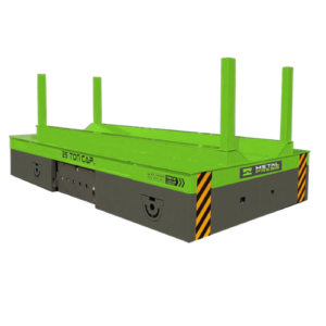
COIL MOVEMENT APPLICATIONS BY WORKFLOW
Storage to production
Move coils from receiving or storage to a defined staging point without mixing pedestrian, forklift, crane, and production traffic unnecessarily. Specify the full route, loaded turning envelope, stopping points, and the support geometry used at pickup and discharge.
Press feeding and decoiler loading
Document the loading axis, mandrel centerline, feeder or straightener location, required coil eye orientation, and the handoff device between the cart and line. The industrial MCC coil transfer cart can be configured around these storage-to-line movements; the receiving press-feeding equipment remains a separate part of the integrated system.
Slitting and cut-to-length lines
Plan how master coils, work-in-process coils, and finished coils move among storage, staging, processing, packaging, and shipping. Include surface-protection requirements, sequence control, queue size, and the effect of coil changeover on line uptime.
Steel service centers and warehouses
Separate travel from orientation change. A supported transfer route can reduce repeated forklift handling, while a purpose-built upender handles controlled 90-degree rotation where the eye orientation must change.
Automated and multi-station workflows
Where automated movement is required, define route permissions, position feedback, obstacle detection, stopping accuracy, battery state, charging, handoff permissives, alarms, and emergency-stop behavior. An AGV-style workflow is a controls and navigation requirement that must be engineered around the actual load and plant environment.
HOW TO PLAN STORAGE-TO-LINE COIL MOVEMENT
Start with the load envelope
Record minimum and maximum coil weight, OD, ID, width, material, surface condition, center of gravity, and allowable contact pressure. Use the extreme combinations, not only a typical coil.
Define travel and duty
Measure the route, grades, joints, floor capacity, turning space, doorways, traffic crossings, cycles per shift, dwell time, and charging window. Compare free-moving or trackless travel with rail-guided motion only after the required path and positioning accuracy are known.
Engineer the support and handoff
Choose a flat deck, V-deck, V-cradle, retention feature, lift table, scissor lift, turntable, or other mechanism from the pickup and discharge geometry. Not every application needs every feature, and each added axis changes controls, safeguarding, maintenance, and cost.
Separate equipment price from total value
Evaluate installed cost together with labor, forklift or crane availability, coil damage, changeover time, downtime, maintenance, energy, battery replacement, operator training, and production gains. The heavy-duty coil-handling selection guide includes a practical comparison and payback method.
Frequently Asked Questions
It supports and moves coils between receiving, storage, staging, processing, and production equipment. The system may include separate machines for horizontal travel, lift, rotation, and line loading depending on the plant layout.
Map receiving, storage, staging, upending, slitting, cut-to-length processing, press feeding, decoiler or uncoiler loading, packaging, and shipping. Include every crane, forklift, cart, saddle, pallet, mandrel, and operator interaction.
Define the coil axis, eye orientation, pickup and discharge heights, centerline, clearance, stopping accuracy, and the device that completes the handoff. If the application needs a dedicated machine, review the MCC product page for configuration and quotation inputs.
It can help when coils repeatedly move along a defined route, forklift availability causes delays, the load needs a purpose-built cradle, or repeated pickup and discharge create damage or safety concerns. The plant risk assessment must still cover all traffic and handoff zones.
Common applications include carbon steel, stainless steel, coated steel, aluminum, copper, and specialty-metal coils. Final suitability depends on load, dimensions, stability, contact surfaces, contamination limits, and surface-protection requirements.
Repeatable movement can reduce staging variation, missed handoffs, coil damage, and unplanned delays. It also gives operators a defined sequence for pickup, travel, stopping, and discharge.
Provide the coil envelope, route drawing, floor information, capacity, cycle rate, deck or cradle concept, pickup and discharge heights, power, controls, remote operation, stopping accuracy, obstacles, safeguards, integration signals, maintenance access, and required documentation.
Treat Every Pickup and Discharge as an Engineered Handoff
A safe route depends on more than travel capacity. Verify how the coil is supported before motion begins, how the receiving device accepts the load, which person or control system authorizes the handoff, and what prevents movement when a condition is not met. Continue to the MCC coil transfer cart product page for the commercial machine, or use the coil transfer-system engineering guide to calculate throughput, buffer, wheel load, and stopping requirements.