

Blog
Engineering a Coil Transfer System: Storage, Upending and Production-Line Loading

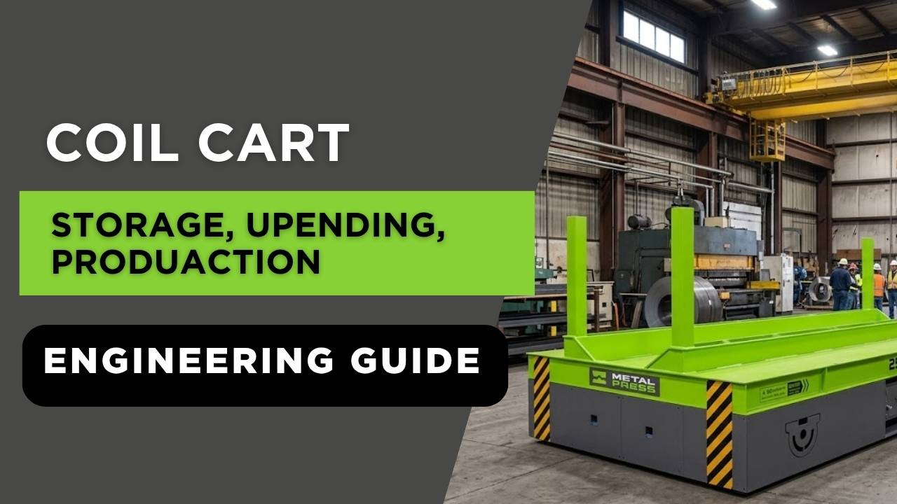
Engineering answer: a coil transfer system should be designed as one material-flow sequence from receiving and storage through orientation, transport, staging and production-line loading. Select the cart and upender together using load geometry, required orientation, travel distance, elevation, cycle demand, traffic controls and the receiving machine.
The MCT coil tipper / upender remains the priority commercial page when the load must rotate. Use the MCC coil transfer cart when it must travel between plant locations.
Two Different Functions, One Coordinated System
Orientation: the MCT rotates a coil between eye-to-sky and eye-to-side. Transportation: the MCC moves the supported coil between storage, staging and production. Many plants need both functions, but they should not be confused.
1. Map the Coil Flow Before Selecting Equipment
Receiving
Unload, identify and inspect the coil.
Storage
Place the coil in its defined supported orientation.
Upending
Rotate 90 degrees when the next operation requires another eye orientation.
Transfer
Move on a rated cart or transport cradle along the planned route.
Staging
Buffer coils near the line without blocking access or traffic.
Line Loading
Interface with a decoiler, slitter, roll former or stamping line.
The map should show every handoff, orientation, elevation, aisle crossing, operator interaction and temporary storage position. Optimizing one machine while ignoring the adjacent handoffs commonly creates queues, extra crane moves or unsafe improvisation.
2. Separate Rotation from Translation
| Equipment | Primary function | Key inputs | Typical destination |
|---|---|---|---|
| Coil tipper / upender | Controlled 90-degree orientation change | Mass, OD, ID, width, center of gravity, starting and final eye orientation | Storage cradle, cart, slitter, decoiler or press-feeding area |
| Coil transfer cart | Controlled horizontal plant movement | Gross load, support geometry, route, travel distance, floor, speed, guidance and power | Staging area or production cell |
| Uncoiler / decoiler | Pays strip from the coil into a process | Coil envelope, mandrel or support, strip tension, line speed and controls | Straightener, feeder, roll former or processing line |
| Crane or forklift | Receiving, lifting or general material movement | Rated capacity, attachment, aisle, visibility, lift plan and operator procedure | Storage, upender or cart handoff |
For common plant configurations, compare the coil transfer cart application guide with the coil-processing application page. These pages support the products; they do not replace the equipment specifications and quotation path.
3. Calculate Required Transfer Throughput
A cart that can carry the heaviest coil may still be too slow for the production rhythm. Model the complete cycle: loading, securing or verifying the load, acceleration, travel, positioning, unloading, empty return and any waiting caused by doors, cranes or shared aisles.
Average transfer capacity
Q = (3600 / tcycle) × mcoil
Q is theoretical transferred mass per hour, tcycle is the complete cycle time in seconds and mcoil is average gross coil mass. Apply actual availability and operational constraints before using the result for production planning.
Required cycles per hour
N = Qdemand / mcoil
N is the required completed transfers per hour, Qdemand is line demand in mass per hour and mcoil is the average usable mass per coil.
Example
If a line consumes 12,000 kg/h and the average usable coil mass is 6,000 kg, the material-flow requirement is two delivered coils per hour. A nominal 30-minute interval is not automatically sufficient: the complete cart cycle must also preserve a buffer for schedule variation, coil changes, inspection and delays.
4. Size the Near-Line Buffer
Buffering decouples the production line from transfer interruptions. An early estimate can use peak demand during the expected replenishment interval.
Minimum buffer-coil estimate
Nbuffer = ceil[(Qpeak × treplenish) / musable]
Use consistent time units. Qpeak is peak material demand, treplenish is the credible replenishment interval and musable is usable mass per coil. Space, fire protection, floor capacity and site rules also limit buffer design.
Do not place extra coils near a line without evaluating floor loading, support cradles, access, emergency routes and the consequences of a damaged or unstable coil.
5. Evaluate Travel Motion and Positioning
Travel time depends on acceleration, maximum speed, braking, route length and positioning requirements. For an idealized trapezoidal velocity profile that reaches maximum speed, a preliminary motion estimate is:
Idealized travel time
t ≈ 2(vmax/a) + [L − (vmax²/a)] / vmax
L is travel distance, a is acceleration magnitude and vmax is maximum speed. The expression assumes the distance is long enough to reach vmax; real controls include jerk limits, safety zones, stopping margins and positioning time.
The supplier should also review rail guidance or trackless steering, wheel loads, floor flatness, expansion joints, gradients, debris, cable management or batteries, operator visibility, audible and visual warnings, and interfaces with doors or automated cells.
6. Check Wheel Loads, Floor Conditions and Stopping Distance
Gross cart capacity does not prove that the existing floor, rails or wheels are suitable. A preliminary average wheel reaction divides the total supported force by the number of load-carrying wheels, but the real reactions may be unequal because of frame stiffness, wheel tolerances, floor unevenness, acceleration, turning and coil eccentricity.
Preliminary average wheel reaction
Ravg = (mcart + mcoil) × g / n
Ravg is average reaction per load-carrying wheel and n is the number of wheels. Obtain the manufacturer’s maximum wheel loads and have the route, floor or rail support reviewed by qualified parties.
Stopping distance also affects aisle controls and protected zones. For constant deceleration, the idealized braking distance is s = v²/(2a). Actual stopping performance must include control response, brake characteristics, floor condition, grade, load distribution and a validated safety margin; do not use the idealized value as a safeguarding distance.
A route survey should document slab thickness and condition, joints, embedded services, pits, drains, slopes, doorway widths, columns, intersections, pedestrian traffic, forklift traffic and emergency access. For rail-mounted carts, include rail alignment, foundations, end stops and the consequences of obstruction.
7. Integrate the Upender with the Receiving Line
| Line type | Typical coil-handling concern | Useful supporting page |
|---|---|---|
| Slitting or cut-to-length | Incoming eye orientation, staging, surface protection and decoiler handoff | Coil processing applications |
| Metal stamping press line | Coil orientation, cart path, decoiler loading, straightener/feeder sequence and line interlocks | Press-feeding coil handling |
| Roll forming or tube mill | Continuous material demand, near-line buffer, coil change rhythm and uncoiler access | Roll-forming and tube-mill coil handling |
| Steel service center | Receiving, storage, slitting, cut-to-length, packaging and shipping flow | Steel service-center coil handling |
8. Controls, Safeguarding and Handoff Logic
Define which machine owns each step and when motion is permitted. Typical interface questions include load-present detection, correct-position confirmation, rotation-complete signals, cart-docked status, receiving-device readiness, guarded-zone status, emergency-stop architecture and recovery after an interrupted cycle.
OSHA’s general machine-guarding requirement addresses protection from hazards created by points of operation and moving parts. A site-specific risk assessment should evaluate the complete integrated cell, not each machine in isolation. Fixed barriers, interlocked access, presence sensing, hold-to-run or two-hand controls, reduced-speed setup modes and administrative procedures must be selected and validated for the actual installation.
9. Coil Transfer System RFQ Checklist
- Maximum/minimum coil mass, OD, ID, width and orientation
- Material surface, banding, edge-protection and support requirements
- Receiving, storage, upending, transfer, staging and line-loading sequence
- Travel distance, route drawing, aisle crossings, floor condition and gradient
- Required deliveries per hour, buffer philosophy and production schedule
- Loading/unloading elevations and positional tolerances
- Manual, powered or automated operation and control ownership
- Power supply, charging, cable management and communications
- Guards, interlocks, sensing, alarms and emergency-stop interfaces
- Installation, commissioning, training, maintenance and future expansion
Frequently Asked Questions
What is the difference between a coil transfer cart and a coil upender?
A transfer cart moves a supported coil between locations. An upender or tipper changes the coil orientation. A coordinated system may use both machines.
How many coils should be stored near a production line?
Estimate the buffer from peak line demand and a credible replenishment interval, then validate floor loading, space, access, fire protection, coil stability and site rules.
Can one cart serve multiple production lines?
Possibly, but the route, scheduling conflicts, cycle time, availability, failure consequences and traffic controls must be modeled. A shared cart can become a single point of production interruption.
Should the upender be installed in storage or near the line?
Place it where the orientation change best supports receiving, storage density, transfer safety and line loading. The correct location comes from mapping the complete process and handoffs.
What should be supplied for a system quotation?
Provide a layout, coil envelope, gross loads, orientations, route and floor data, production demand, handoff elevations, cycle expectations, controls, safeguarding requirements and future expansion plans.
Keep the Coil Tipper as the Priority Product
If the workflow requires a 90-degree coil orientation change, review standard MCT capacities and options on the MetalPress coil tipper product page. Add the MCC cart when controlled horizontal transportation is also required.
References and Engineering Resources
- MetalPress MCT Coil Tipper / Coil Upender
- MetalPress MCC Coil Transfer Cart
- OSHA 1910.176 — Handling materials, general
- OSHA 1910.212 — General requirements for all machines
- ISO 12100:2010 — Safety of machinery, risk assessment and risk reduction
Engineering note: This article provides planning concepts, not a final machine design or site-specific safety determination. Actual equipment must be selected and validated from the complete load, duty cycle, installation, safeguarding, controls and applicable-code requirements.