

Blog
How to Choose a Die Cart: Capacity, Height and Transfer Method

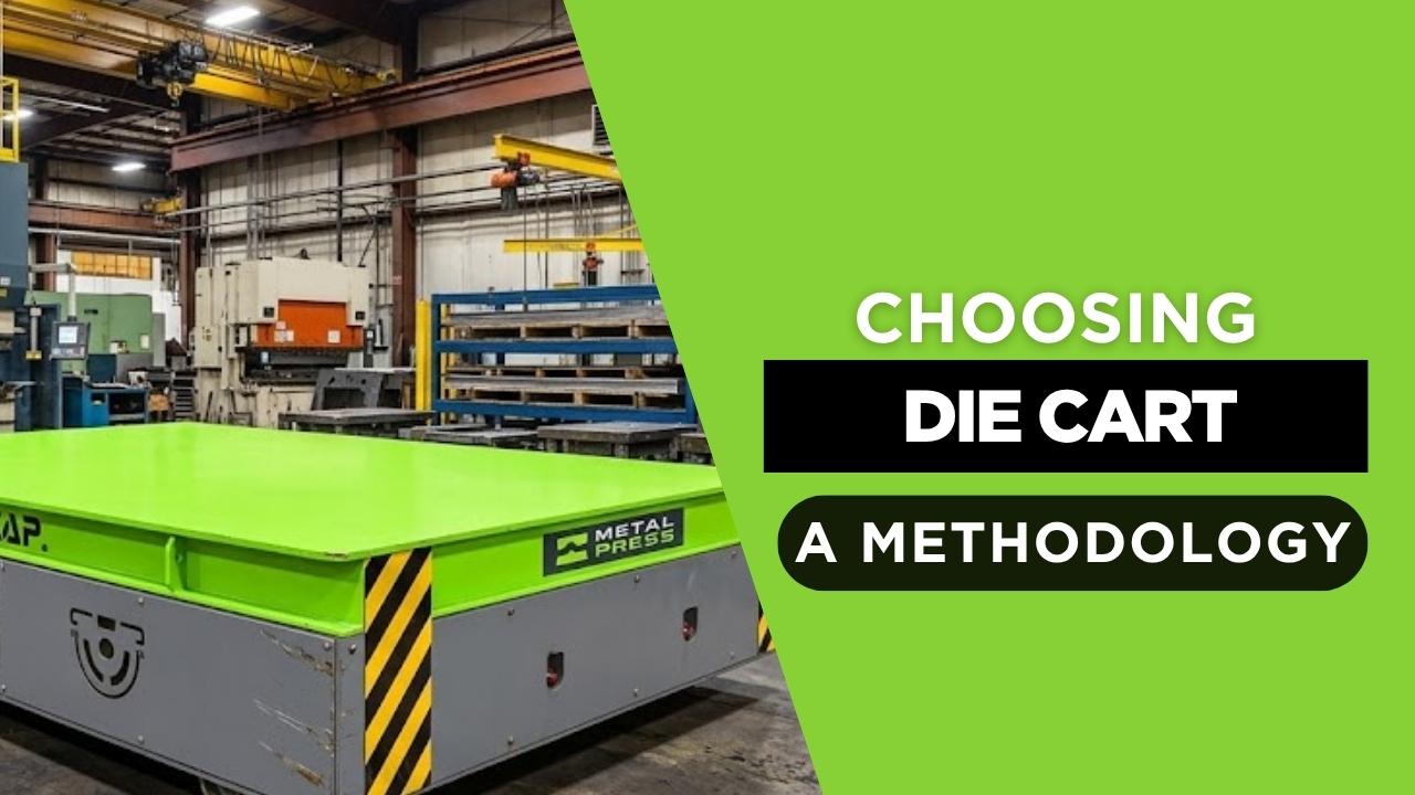
Direct answer: choose a die cart from the complete tooling envelope and transfer workflow—not nominal tonnage alone. Verify maximum weight, dimensions, load center, support points, deck size, pickup and discharge height, aisle width, turning space, floor loading, travel distance, cycles per shift, battery duty, stopping accuracy, and every rack, press, molding-machine, crane, forklift, or upender handoff.
A cart that only transports tooling is different from a die-changing cart with lift, powered rollers, push-pull, docking, or press-bolster loading. Specify each required motion and interface explicitly. For MetalPress commercial capacities and features, use the MMC die cart and mold transfer cart product page.
Die Cart, Mold Cart, Transfer Cart and Die Handler: What the Names Mean
Die cart, die transfer cart, mold cart, mold transfer cart, die handling cart, die transporter, mold transporter, and die transfer trolley commonly describe equipment that supports horizontal tool movement. Die handler is broader and may include lifting, docking, push-pull transfer, rider or walk-behind operation, or other handling axes.
The safest specification describes the work: pickup location, travel, steering, stopping, height change, deck transfer, docking, retention, and discharge. That keeps a buyer from assuming that every powered cart has a hydraulic lift, roller deck, rigid-chain pusher, or press interface.
Six Steps for Selecting a Die or Mold Cart
Define the Tooling Envelope
Record weight, length, width, height, load center, weight distribution, support points, die shoe, and allowable contact surfaces.
Map the Complete Route
Measure aisle width, turns, grades, joints, doors, crossings, floor capacity, traffic, pickup points, and discharge points.
Match Transfer Height
Document rack, cart deck, press bolster, molding-machine, maintenance-bench, and upender interfaces.
Choose Travel & Control
Compare trackless or guided travel, steering, remote or pendant operation, speed, stopping accuracy, and position feedback.
Specify Each Handoff
Define lift, rollers, ball transfer, push-pull, docking, retention, alignment, and the conditions that authorize movement.
Validate Duty & Safety
Calculate cycles, battery runtime, charging, maintenance access, traffic controls, safeguards, training, and risk-assessment actions.
Capacity Is More Than Maximum Die Weight
Nominal capacity is the starting point. The engineering review also needs the tool’s load center and weight distribution, because wheel and frame loads can be uneven even when the total weight is below the nameplate rating. Verify the supported footprint, center-of-gravity range, deck stiffness, local contact pressure, wheel loads, and floor capacity.
For a simplified first check, average static wheel load is:
Average wheel load = (tool weight + cart weight) ÷ number of load-bearing wheels
This average is not a final design load. Acceleration, braking, floor unevenness, turns, load offset, wheel tolerances, and safety factors create unequal and dynamic loads that the manufacturer and facility engineer must evaluate.
Match Deck Height, Transfer Height and Press Interface
A transport-only cart can receive a die by crane or forklift and discharge it the same way. Direct rack or press transfer is different. It may require adjustable height, lift, docking pins or brackets, alignment guides, powered rollers, ball-transfer surfaces, a rigid-chain push-pull mechanism, or another powered transfer method.
Document minimum and maximum transfer height, press bolster height, shutoff position, approach direction, die base, rail or roller spacing, allowable gap, docking tolerance, side or front loading, and the sequence that prevents movement before the connection is secure. Availability of lift, roller-deck, push-pull, side-shift, or docking functions must be confirmed in the quotation.
Trackless vs. Rail-Guided and Manual vs. Powered Travel
| Configuration | Best fit | Key planning issue |
|---|---|---|
| Trackless powered cart | Flexible routes and several pickup/discharge points | Turning envelope, floor condition, traffic, navigation, stopping, and battery duty |
| Rail-guided transfer cart | Fixed repeatable path and defined stations | Rail/foundation work, crossing protection, docking, and route inflexibility |
| Manual cart | Lower loads, short moves, and infrequent duty where force is acceptable | Push/pull force, grades, control, braking, operator ergonomics, and risk assessment |
| Powered walk-behind or remote cart | Repeated heavy-tool movement with operator control near the route | Visibility, safe position, controls, stopping distance, and pedestrian separation |
| Rider or automated handler | Specialized long routes or integrated systems | Operator station or navigation, traffic control, controls integration, and additional safeguards |
Roller Deck, Ball Transfer, Push-Pull and Docking
A gravity roller deck reduces sliding friction but still needs a controlled force and a safe method to stop and retain the tool. A powered roller deck adds a driven transfer axis. Ball-transfer tops allow movement in more than one horizontal direction but require a compatible tool base and positive retention. A push-pull device moves the tool across a bridge or interface; its attachment, stroke, force, chain or actuator, and release sequence must match the die and press.
Docking locates and secures the cart relative to a rack or press. A complete design coordinates mechanical engagement, height, alignment, permissives, brakes, transfer motion, retention, and emergency response. These terms describe different functions and should not be used interchangeably.
Die Cart vs. Forklift and Overhead Crane
| Method | Typical strength | Limitation to evaluate |
|---|---|---|
| Dedicated powered die cart | Stable support and repeatable movement on defined routes | Installed route, floor, charging, handoffs, controls, and maintenance |
| Forklift | Flexible pickup and use across many tasks | Attachment rating, visibility, load stability, traffic, availability, and tooling damage |
| Overhead crane | Vertical lifting within crane coverage | Crane contention, rigging time, suspended-load exposure, and route coverage |
| Pallet jack or manual cart | Simple short-distance movement for suitable loads | Operator force, braking, grades, stability, capacity, and control |
A plant may use several methods. The question is which device should own each step. A dedicated cart is most valuable when the same heavy-tool move repeats often enough that controlled travel, a purpose-built deck, predictable stopping, and reduced crane or forklift contention create measurable benefit.
Connect the Cart to the Die-Change Workflow
The cart is one part of changeover. A complete plan includes production shutdown, old-tool disconnection, removal, outgoing-tool staging, incoming-tool verification, transport, orientation, press access, transfer, alignment, clamping, utilities, guarding, trial, and restart. Review the die changeover applications page for the broader sequence and the heavy tooling movement page for route and handoff planning.
Pre-staging can shorten waiting only when the next tool, cart, operators, fasteners, clamps, connections, program, material, and inspection requirements are ready before shutdown. Measure actual tasks instead of assigning all changeover savings to the transport equipment.
Estimate Cycle Time, Payback and Total Cost
Measure the current cycle from pickup authorization through safe discharge. Annual handling hours are:
Annual handling hours = moves per year × minutes per move ÷ 60
If a proposed system reduces the cycle, annual hours saved are:
Annual hours saved = moves per year × (current minutes − proposed minutes) ÷ 60
Simple payback is:
Payback period = installed project cost ÷ annual net savings
Total cost of ownership should include acquisition, engineering, installation, floor or rail work, integration, energy, batteries, maintenance, training, downtime, and residual value. Count production benefit only when the time saving removes a documented bottleneck or increases usable line availability.
Information to Include in a Die Cart RFQ
- Minimum and maximum die or mold weight and dimensions
- Load center, weight distribution, support points, and surface-protection requirements
- Pickup and discharge locations, heights, directions, and receiving equipment
- Route drawing, aisle width, turns, slopes, joints, floor condition, and floor capacity
- Moves per shift, loaded and empty travel distance, dwell time, and charging window
- Trackless or guided travel, steering, speed, controls, remote operation, and stopping accuracy
- Deck, lift, rollers, ball transfer, push-pull, docking, retention, and alignment requirements
- LiDAR, safety edge, rails, alarms, emergency stops, traffic controls, and required risk reduction
- Integration signals, plant electrical standards, documentation, training, and acceptance testing
Related MetalPress Equipment and Guides
MMC Die Cart & Mold Transfer Cart
Review standard capacities, construction, powered travel, controls, options, and quotation inputs.
Heavy Tooling Movement Applications
Map storage, toolroom, maintenance, staging, press, and molding-machine handoffs.
Die Changeover Applications
Connect transport, orientation, alignment, clamping, verification, and production restart.
Frequently Asked Questions
How do I choose the capacity of a die cart?
Use the maximum verified tooling weight plus the manufacturer’s engineering criteria, then check dimensions, load center, weight distribution, deck support, wheel loading, floor capacity, and the complete route.
What is the difference between a die cart and a die handler?
A die cart primarily supports horizontal transport. Die handler is a broader term that may include lift, push-pull, docking, rider, walk-behind, or other functions. Define the required axes and interfaces instead of relying on the name.
Should the die cart deck match press bolster height?
Only when the cart participates directly in press loading. In that case, document minimum and maximum transfer height, bolster geometry, alignment, docking, load support, and the method that moves the die across the interface.
Is a roller deck or push-pull system always required?
No. The transfer mechanism depends on the press, rack, die base, friction, transfer direction, height, and approved handling sequence. Roller, ball-transfer, powered deck, push-pull, lift, and docking features must be specified separately.
When is a trackless powered die cart a good fit?
It can fit repeated in-plant routes where tooling needs a stable support surface, powered travel, flexible steering, and reduced dependence on forklifts or cranes. Floor capacity, aisle clearance, traffic, and stopping points must be verified.
How should die-cart ROI be calculated?
Compare installed project cost and ownership costs with documented labor savings, released crane or forklift time, avoided tooling damage, reduced changeover delay, maintenance, battery replacement, and production benefit. Show every assumption.
Engineering Note
This guide supports early planning. Final equipment capacity, floor loading, transfer interfaces, controls, safeguards, and operating procedures require application-specific engineering and the facility’s risk assessment.