

Blog
Die Cart Floor Loading and Route Surveys for Heavy Tooling

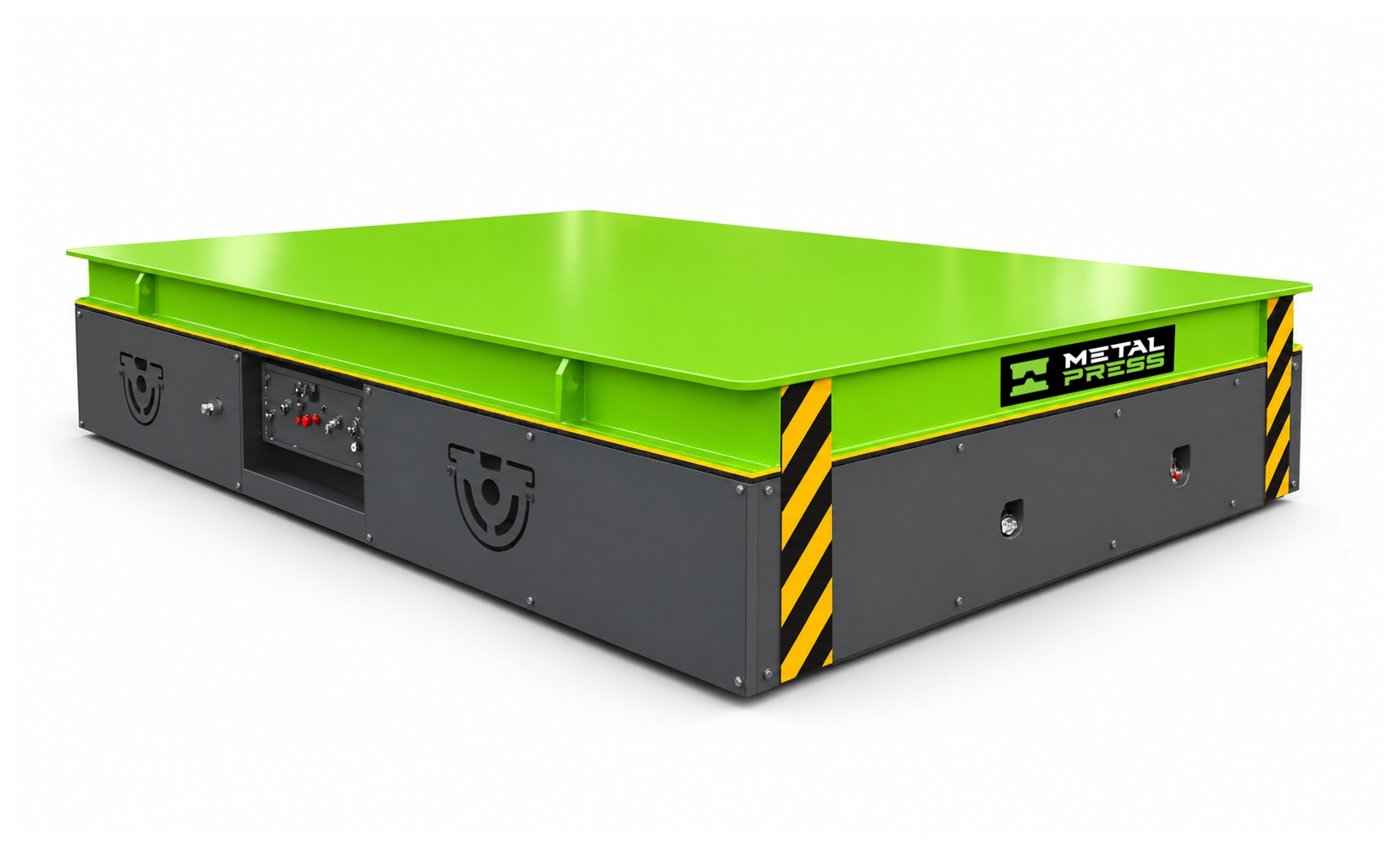
A die cart route survey connects the tooling load to the floor, travel envelope and receiving equipment. For heavy tooling movement, evaluate the loaded vehicle, individual wheel reactions, slab and crossing conditions, steering clearance and each pickup or discharge point. A cart capacity rating is not a floor approval. This briefing explains the information the equipment supplier and facility engineer need before a route is accepted.
For equipment models and configuration enquiries, review the MMC die cart and mold transfer cart. Use the die-cart selection guide for the overall buying and application checklist.
Separate payload capacity, wheel load and floor capacity
The die or mold is only one part of the moving load. Include the cart, battery, fixtures and carried accessories when establishing the loaded vehicle mass. The maximum permitted tooling load remains a separate machine limit and depends on the specified support arrangement and load center.
Wheel reactions are the forces transmitted through the individual wheels or wheel groups. They depend on vehicle geometry, suspension or equalization, tooling position and the operating condition. Average pressure calculated over the deck or vehicle footprint hides these concentrated forces. It cannot demonstrate that the slab, a trench cover or a bridge plate can support the cart.
Request the wheel-load envelope before reviewing the slab
Ask the cart supplier for the loaded and unloaded wheel arrangement, wheel spacing, maximum wheel or wheel-group reactions, wheel material, contact information and relevant operating cases. Obtain the conditions behind the figures: centered or eccentric load, steering position, acceleration, braking and permitted gradients.
The facility engineer then needs the floor construction and condition: slab-on-ground or suspended construction, drawings, reinforcement or post-tensioning information where applicable, joints, edges, openings, repairs and support conditions. A suspended floor requires a different structural review from a slab bearing on ground. Do not apply a generic allowable pressure or concrete thickness to both.
An illustrative wheel-load calculation—and its limits
Example only, not an MMC specification: assume a 20,000 kg tool, an 8,000 kg cart and four equally loaded supports. The total static weight is approximately 28,000 × 9.81 = 274,680 N, or 274.7 kN. An ideal equal share is about 68.7 kN per support.
That equal-share figure is not a maximum design wheel load. Actual loading can be uneven because of load-center offset, vehicle construction, steering, floor unevenness and motion. Dividing the payload alone by four would omit the cart mass as well as those effects. Use supplier-issued reactions for the actual configuration; the structural engineer determines the appropriate design cases and acceptance criteria.

MMC Die Cart & Mold Transfer Cart
Review published models, battery-powered travel and configuration requirements for horizontal movement of heavy dies, molds and tooling. Match the cart, route, duty and handoffs to the actual application.
Survey the complete travel route
- Measure the narrowest clear opening, corner, doorway and aisle with the tool on the deck—not only the empty-cart width.
- Record loaded travel distance, intersections, pedestrian interfaces, visibility restrictions and designated stopping areas.
- Map joints, thresholds, cracks, drains, trenches, pits, covers, ramps and changes in level. Photograph and dimension each constraint.
- Identify floor contamination, loose material and conditions affecting traction or wheel contact.
- Include empty return travel, charging access, maintenance access and an alternative response to a blocked route.
Multidirectional travel can help positioning, but it does not prove that a loaded cart fits every corner. Review the complete swept envelope, tooling overhang and any required operator clearance with the supplier. Confirm gradients, transitions and stopping arrangements against the supplied machine documentation.
Treat joints, covers and handoffs as local checks
A route that is acceptable across an open floor can still be unsuitable at one cover, threshold or slab edge. Repeated wheel traffic at discontinuities can create different local demands from a stationary load. Identify who owns the supporting drawings and who can approve each crossing.
At a storage rack, maintenance bench, upender or production machine, document support height, tool retention, alignment and the point at which load support changes. A roller deck, lift, bridge plate, push-pull device or docking interface must be confirmed as a separate engineered function. Transporting a tool to a press does not establish a complete press-loading capability.
Build a route-survey package for the equipment review
Give every route segment an identifier and retain the survey revision. Include plan drawings, photographs, measured constraints, floor information, tool envelopes and operating cases. Record open issues rather than treating a missing floor drawing as acceptance.
- Equipment supplier: vehicle mass, geometry, reaction data, operating limits and interface requirements.
- Facility or structural engineer: floor and crossing assessment against the proposed loading and traffic.
- Operations and safety team: traffic separation, operating sequence, access control and site risk assessment.
- Project owner: written closeout of constraints, approved configuration and change-control responsibilities.
Validate the agreed route during commissioning
Use the agreed commissioning procedure and representative loading conditions to check travel clearances, positioning, stopping, handoffs and operating access. A successful demonstration does not replace the structural assessment. Record deviations and resolve them before changing the agreed operating envelope.
Reassess when tool mass or load center changes, the route is modified, a cover is replaced, or the floor condition deteriorates. Keep the accepted survey with the cart documentation so later teams do not infer approval from the machine nameplate.
Project review checklist
| Survey input | Why it matters | Who confirms it |
|---|---|---|
| Tool and cart mass; load center | Defines the loaded operating cases | Tool owner and cart supplier |
| Wheel arrangement and reaction envelope | Connects the vehicle to concentrated floor loads | Cart supplier |
| Slab, joints, edges and covers | Checks local and overall support | Facility/structural engineer |
| Loaded swept envelope and route constraints | Checks travel and operator clearance | Supplier and site team |
| Pickup and discharge interfaces | Defines support transfer and retention | Equipment owners and supplier |
Continue planning the tooling workflow
- How to choose a die cart: capacity, height and transfer method
- Heavy tooling movement and storage-to-press applications
- Die-cart duty cycle and battery charging for multiple shifts
Use the MMC product page for the commercial equipment specification. These articles provide planning inputs, not approval of a floor, battery system or operating procedure.
Frequently Asked Questions
Can I use the die weight to calculate floor loading?
Not alone. Include the complete loaded cart and obtain the supplier’s wheel-reaction envelope. The floor assessment also needs the slab and crossing construction, condition and relevant operating cases.
Does a high-capacity die cart require a specific concrete thickness?
There is no universal thickness established by the cart capacity. Slab type, support, reinforcement, joints, wheel geometry, loading cases and condition need a project-specific assessment.
Does multidirectional steering eliminate aisle-width checks?
No. Check the swept envelope of the loaded vehicle, tooling overhang, turns, stopping areas and operator clearances for the actual route.
Are floor pressure and wheel load the same?
No. Wheel load is a force; contact pressure is force divided by a contact area. Neither a deck-footprint average nor contact pressure alone establishes the structural adequacy of a floor.
Technical references and application review
- Toyota Material Handling wheel-selection guide: Background on how wheel arrangement and operating surface affect load distribution. It is not an MMC wheel-load specification.
- Steel Deck Institute Floor Deck Design Manual, section 2.6: Background on special design considerations for suspended floor systems exposed to repeated heavy wheeled traffic; not a die-cart floor approval.
The references explain general engineering principles and manufacturer-specific examples. They do not establish that the referenced equipment, battery or charger is supplied with an MMC cart. Confirm the final configuration with MetalPress and the responsible site professionals.