
HEAVY TOOLING MOVEMENT APPLICATIONS
Plan storage-to-press travel, toolroom movement, staging, mold-machine handoffs, and heavy-tool transport before selecting equipment.
Heavy Tooling Movement and Production-Equipment Handoffs
MAP THE TOOLING ROUTE BEFORE SELECTING EQUIPMENT
Heavy tooling movement begins with a route map. Document where each die or mold is stored, inspected, repaired, staged, rotated, and installed. Every pickup and discharge point should define tooling weight, dimensions, load center, support height, aisle clearance, floor condition, and the equipment that receives the load.
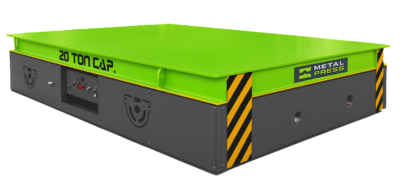
Separate horizontal travel from lift, rotation, and machine transfer. A cart changes the tool’s location; an upender changes its orientation; a lift or powered deck changes the transfer geometry. When a dedicated powered vehicle is required, the MMC die cart and mold transfer cart is the priority commercial source for capacities, construction, controls, options, and quotation details.
Use this application page for storage-to-press movement, toolroom-to-production transport, maintenance staging, die pre-staging, injection-mold movement, and line handoffs. Final equipment selection follows the verified load envelope, route, duty cycle, risk assessment, and plant standard.
GET A FREE QUOTE TODAY

HEAVY TOOLING MOVEMENT BY WORKFLOW
Storage to press or molding machine
Move tooling from racks or staging to production through a defined route. Record the press bolster or machine interface, but treat docking, lifting, roller transfer, and push-pull as separate functions that must be confirmed.
Toolroom and maintenance movement
Connect storage, benches, cleaning, inspection, welding, spotting, repair, and production-preparation zones. Surface protection, load retention, technician access, and pickup support are part of the workflow.
Die changeover and pre-staging
Stage the next tool close to production without blocking aisles or service access. The die changeover applications guide connects transport with orientation, alignment, clamping, and restart.
Injection-mold movement
Plan mold travel among storage, maintenance, tryout, and molding machines. Include cooling connections, mold protection, machine access, and the approved lifting or transfer method.
Integrated handling systems
Where equipment communicates with a press, rack, upender, crane, or automated cell, define permissives, position feedback, stopping accuracy, alarms, emergency stops, and who authorizes each handoff.
HOW TO PLAN A HEAVY TOOLING MOVEMENT SYSTEM
Start with the complete load envelope
Record maximum and minimum tool weight, length, width, height, load center, weight distribution, contact surface, and allowable support points. Use the extremes—not only the typical tool.
Define travel, floor, and duty
Measure route distance, aisle width, turns, grades, joints, floor capacity, crossings, cycles per shift, dwell time, stopping points, and charging opportunities.
Engineer every handoff
Specify pickup and discharge height, rack or bolster geometry, lift or transfer axis, docking, alignment, retention, controls, safeguarding, and the conditions required before movement begins.
Compare installed value
Evaluate equipment and integration cost together with labor, forklift or crane availability, tooling damage, changeover delay, maintenance, batteries, and production losses. The die-cart buyer’s guide provides a structured comparison and simple payback method.
Frequently Asked Questions
It is the planned combination of storage, support, transport, lift, rotation, staging, and production-equipment handoffs used to move dies, molds, and other large tools through a facility.
Map receiving, storage, racks, toolroom benches, maintenance, spotting, upending, staging, press or molding-machine loading, production removal, and return to storage.
Horizontal transport changes location. Press loading may also require matched transfer height, docking, lift, powered rollers, push-pull, alignment, controls, and safeguarding. Those functions must be specified separately.
Metal stamping, injection molding, die casting, automotive, appliance, aerospace, tool and die shops, and other operations with heavy production tooling can benefit from a defined movement workflow.
Pre-staging positions the next approved tool and required handling equipment before shutdown. It can reduce waiting, but the full changeover still includes removal, inspection, cleaning, alignment, clamping, connections, verification, and restart.
Evaluate one when heavy tooling repeatedly follows a defined in-plant route and needs a purpose-built support surface, controlled powered travel, repeatable stopping, or reduced contention for forklifts and cranes. See the MMC product page for commercial details.
Provide tooling weight and dimensions, load center, pickup and discharge geometry, route and floor information, cycle rate, deck or support concept, power, controls, battery duty, safeguards, integration signals, maintenance access, and documentation requirements.
Treat Each Pickup and Discharge as an Engineered Handoff
Verify how the tool is supported before movement, how the receiving device accepts it, which person or control system authorizes the handoff, and what prevents motion when a required condition is not met. Continue to the MMC die cart product page for the commercial equipment or the die-cart selection guide for capacity, height, route, transfer-method, cost, and ROI planning.