
MULTI-BEND SHEET METAL PARTS
Plan flanges, channels and folded profiles around bend sequence, tooling clearance and consistent locating references.
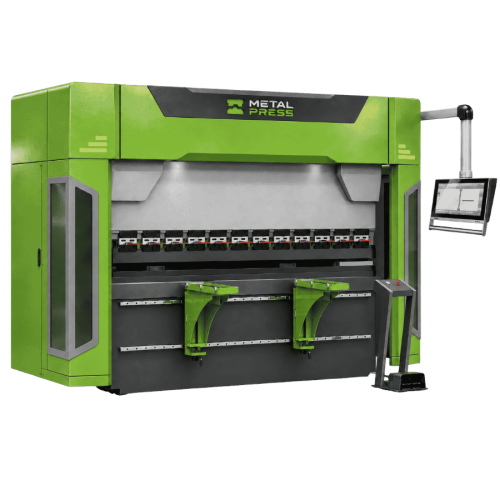
Fabrication Equipment for Multi-Bend Sheet Metal Parts
Multi-bend sheet metal fabrication plans the press brake bend sequence for channels, trays, covers and return-flange components. Channels, trays, covers and return-flange components must be planned as a sequence, because each completed bend changes the space available for the next operation. Start with the formed drawing and an approved flat pattern, not a list of bend angles alone.
Review Titan CNC press brake against the actual drawings, material and production requirements. Find related workflows in the fabrication applications hub.
For a proposed channel with return flanges, review the intermediate shape after each bend: which face locates against the backgauge, whether the existing flange clears the tools, and how the part is removed. This drawing-based review is more useful than selecting a machine from final dimensions alone.
Plan the Complete Bend Sequence
Review every intermediate part shape, including tool approach, backgauge access and removal of the finished component. The final shape can fit the machine while an earlier forming step does not.
CNC Bending for Flanges, Channels & Folded Parts
Define bend length, material strength and thickness, inside radii and flange dimensions for each operation. Select tooling and working clearance around the entire part envelope. Return bends and tall sidewalls can limit access even when the required force is within the machine rating.
Review the Titan configuration for tooling height, opening, stroke, backgauge arrangement and part support. Confirm special profiles using the actual drawing rather than assuming a standard tool set can form every geometry.
View Titan CNC press brake models and specifications for the relevant equipment configuration.
Review press brake tooling selection and bending methods when checking flange access, tool interference and the complete bend sequence.
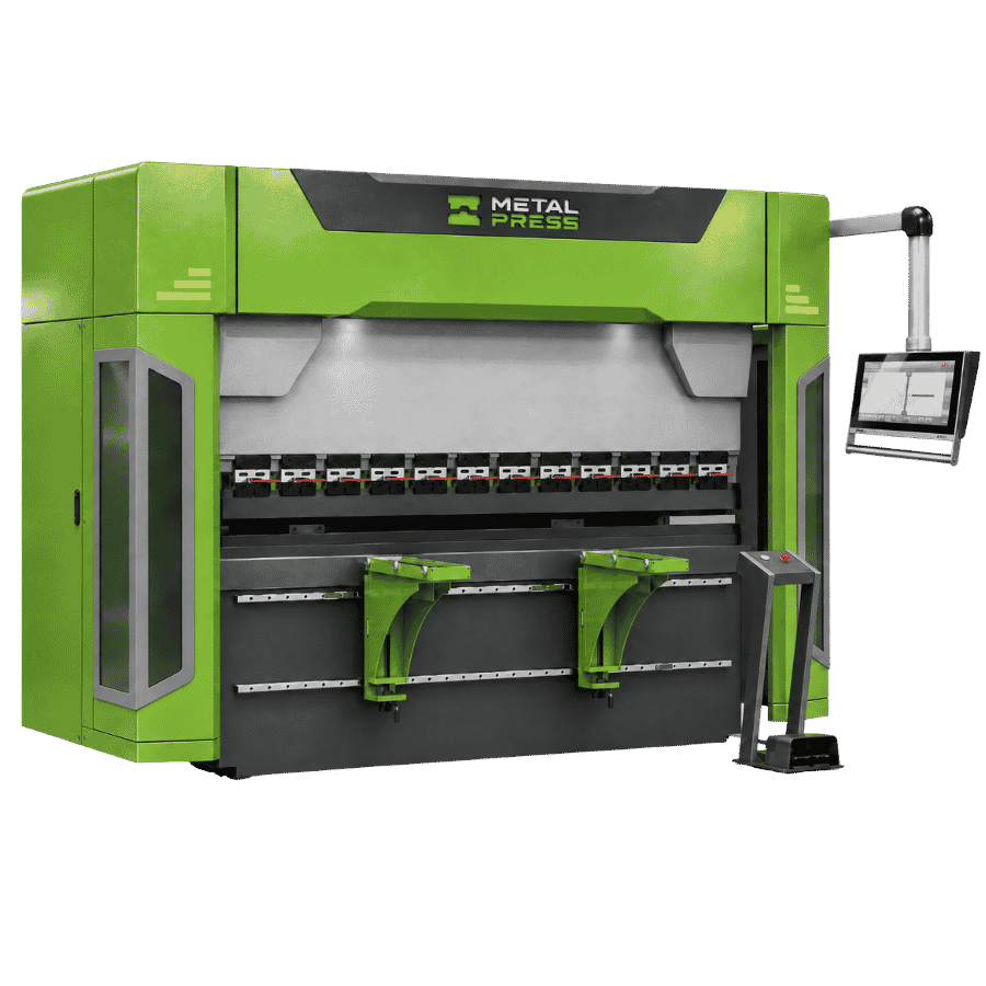
Plan the Multi-Bend Sheet Metal Parts Workflow
Flat pattern & bend references
Confirm bend allowances and identify the datum edges used to locate the blank. Check which dimensions are controlled by cutting and which depend on the forming setup.
Tool interference & part removal
Review the workpiece at every bend, including existing flanges and the path used to remove it from the tools. Check whether segmented or special tooling is needed.
Gauging & repositioning
Define locating surfaces for each bend and plan when the part must be rotated or flipped. Avoid relying on an edge that becomes inaccessible later in the sequence.
First-part verification
Check angles, flange dimensions, overall geometry and fit against the drawing before releasing the batch. Record the approved setup and inspection references for repeat work.
Material & Application Requirements
Material grade, strength, thickness and direction can affect springback and the selected bend radius. Cosmetic faces need a defined tool-contact and handling plan. Establish the setup on representative material rather than applying one bend allowance to every grade.
Related application planning: sheet and plate blank preparation and enclosure and cabinet fabrication.
Prepare Your Fabrication Enquiry
Provide the formed drawing, flat pattern, bend radii, shortest flanges, tallest sidewalls and tightest dimensional relationships. Include quantities, surface requirements, tooling already available and the largest part to be supported.
Discuss your multi-bend sheet metal parts requirements with MetalPress to review the machine configuration, tooling and production route.
Multi-Bend Sheet Metal Parts Questions
Each bend changes access to the tools and locating surfaces. A workable sequence must consider tool collision, gauging, handling and part removal, not just the final geometry.
No. Return flanges, narrow channels and deep forms can need different tooling or a different process. Review the drawing and intermediate shapes before confirming the setup.
Start with Titan CNC press brake. Compare the applicable ratings, tooling, access and support with the actual part drawing.
Provide the formed drawing, flat pattern, bend radii, shortest flanges, tallest sidewalls and tightest dimensional relationships. Include quantities, surface requirements, tooling already available and the largest part to be supported.
PLAN YOUR NEXT
Share your drawings and material requirements to review equipment, tooling, access and handling for this application.