
TRIM PRESS APPLICATIONS
Flash, gate and runner removal for castings, forgings and molded parts. Plan the trim die, press cycle and part-handling workflow together.
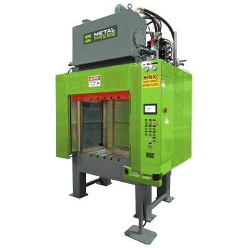
Plan the Trimming Operation Around the Part
A trimming press separates flash, gates, runners, overflows or other excess material from a part using a matched trim tool. In a die-casting cell, trimming follows casting and part removal; it does not replace the die-casting machine that produces the casting.
For die-casting flash removal, start with the MPTP hydraulic trim press and evaluate the part, die and handling cycle. For help selecting a configuration, send your trimming requirements with the part drawing, material, cut perimeter and production target.
Trimming Applications and Material Checks
| Application | Operation | Inputs to review |
|---|---|---|
| Die-cast aluminum, zinc and magnesium | Remove gates, runners, overflows and flash after casting. | Review alloy and part temperature, cut locations, fragile features, support points and the sequence for separating casting and scrap. |
| Forged metal components | Trim flash from a forging using application-specific tooling. | Define hot or cold trimming conditions, flash thickness, cutting load, tool temperature, energy release and permitted frame loading. |
| Molded plastics and composites | Remove molding flash or trim an edge/profile where press trimming suits the material. | Review reinforcement, thickness variation, edge-quality criteria, particle control and sample trials with the actual tool and material. |
Review Equipment for the Trimming Cell
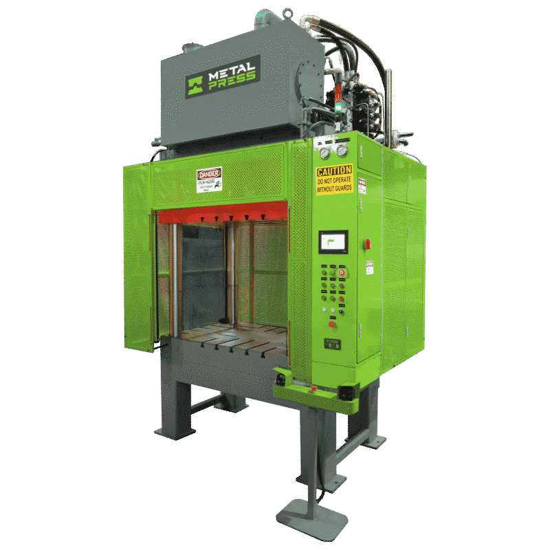
MPTP Hydraulic Trim Press
Purpose-built trim-press equipment for evaluating die-casting flash removal, part ejection, scrap discharge and integration requirements.

MTP 4-Post Hydraulic Press
A four-post production platform to evaluate when the trim tool, working area and additional operations call for a general hydraulic configuration.
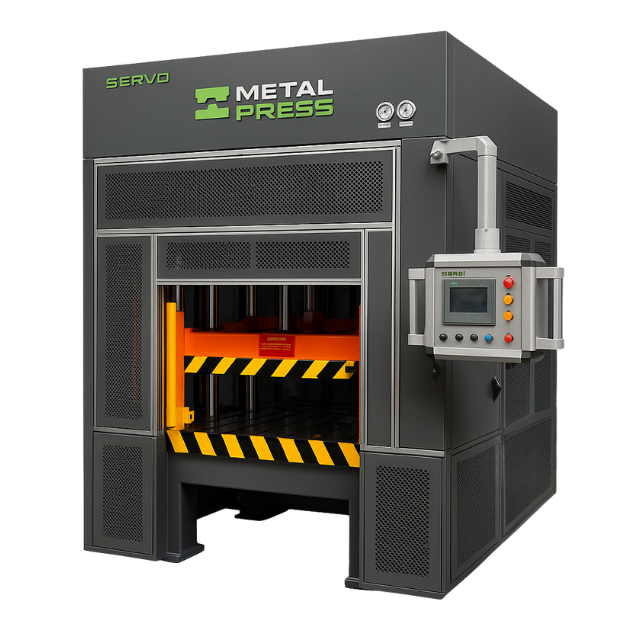
MTP-SV 4-Post Servo-Hydraulic Press
Evaluate a servo-hydraulic drive when the project calls for a defined approach, cutting and return profile together with the required tooling and controls.
Compare Press Configurations for Your Trim Tool
| Press configuration | When to evaluate it | Selection checks |
|---|---|---|
| Dedicated hydraulic trim press | Die-casting trimming, flash removal and handling functions. | Part orientation, trim tool, ejectors, scrap openings, unloading and the full cell cycle. |
| 4-post hydraulic press | A general hydraulic platform for a trim tool and associated production requirements. | Working area, opening, stroke, permitted loading, guidance and control sequence. |
| 4-post servo-hydraulic press | Programmable hydraulic motion for an application-specific trimming cycle. | Required motion stages, pressure feedback, decompression, die recipes and auxiliary actions. |
| Straight-sided servo-hydraulic press | Projects whose force and tool envelope call for evaluating a straight-sided frame. | Platen size, tooling weight, guidance, allowable load location and response at breakthrough. |
For a recurring production operation suited to crank-driven equipment, compare single-point and double-point mechanical presses, or single-point and double-point servo-mechanical presses. Review force at the working position, available energy, stroke, tool footprint and breakthrough loads for the actual operation.
Define Six Inputs for a Trimming-Press Enquiry
Part and material
Send the alloy or polymer specification, casting/forging condition, trimming temperature, drawing and sample-part information.
Cut and tool
Define the edges cut together, gate and flash sections, tool clearances, locating surfaces, part support and tool weight.
Working envelope
Provide die footprint, shut height, stroke, daylight, clamp layout, tool-change access and the required scrap openings.
Force and motion
Define the cutting-load estimate, slide-speed stages, permitted breakthrough response and any ejector or core-punch sequence.
Cell and output
Include loading/unloading time, part orientation, robot or manual workflow, scrap handling and the upstream production cycle.
Safeguarding and acceptance
Agree the risk assessment, guarding and interlock concept, utilities, acceptance samples, edge-quality criteria and documentation.
Estimate Cutting Force with the Actual Material Data
For an initial straight-shear estimate, cutting force is the sheared area multiplied by the material shear strength:
F ≈ L × t × τ
L is the total cut length engaged at the same time, t is the section thickness at the cut, and τ is the material shear strength at the relevant condition. Sum the contributions when thickness or material varies between cuts.
Use material data for the actual alloy, temperature and condition rather than a generic “aluminum” or “plastic” preset. Tool shear angle, staged cuts, stripping/ejection loads, wear and breakthrough behavior also enter the engineering review. The estimate supports tool and press selection; it is not a machine recommendation by itself.
US customary units
With cut length and thickness in inches and shear strength in psi, the result is in pounds-force. Divide by 2,000 for US ton-force.
Metric units
With cut length and thickness in millimetres and shear strength in N/mm² (MPa), the result is in newtons. Divide by 1,000 for kN or 9,806.65 for metric tonne-force.
Control Edge Quality, Breakthrough and Scrap Flow
Support and alignment
Support the part close to the cut and check locating repeatability, trim-die guidance and clearance. Set measurable criteria for residual flash, burr height and part distortion.
Breakthrough response
As the cut separates, stored energy can release suddenly. Evaluate speed through the cut, tool support, permitted press loading and any required cushioning or deceleration.
Part and scrap flow
Define how the trimmed part and gates/runners leave the tool. Evaluate ejectors, chutes, conveyors, sensing and robot sequence so the next cycle starts with the die area clear.
Investigate Common Trimming Problems
| Observed result | Review with the tooling and equipment teams |
|---|---|
| Residual flash or heavy burrs | Tool wear, clearance, alignment, cut penetration and part location. |
| Part distortion or cracking | Support points, material/temperature, loading sequence and tool geometry. |
| Tool chipping or vibration | Breakthrough load, guidance, permitted frame loading, tool material and wear. |
| Cell interruptions | Scrap escape path, ejectors, sensing, robot timing and interlocks. |
See a Custom Trim-Press Engineering Project
Review the documented custom 35-ton trim-press project for the enquiry, design and precommissioning workflow. The related design and assembly article describes the same project, including the machine and part-handling configuration.
Use the project to discuss the drawings, tooling interfaces, acceptance checks and handover needed for your installation. Review the MPTP trim-press product specifications for the available machine family rather than treating one project as a specification for every model.
Discuss Your Trimming Application
Send the part and trim-tool drawings, material and trimming temperature, cut perimeter and section thickness, force estimate, working envelope, stroke/daylight, cycle target and the complete loading, ejection and scrap-handling concept.
Include guarding, robot interfaces, utilities and acceptance criteria. If the press family is already selected, identify the MPTP trim press, MTP hydraulic press or MTP-SV servo-hydraulic press in your enquiry.
Trimming-Application Questions
Is a trim press the same as a die-casting machine?
No. The die-casting machine forms the casting. The trim press is downstream equipment used to separate gates, runners, flash and other excess material from that casting.
What determines the required trim-press force?
The engaged cut length, thickness and material shear strength provide a starting estimate. The actual tool geometry, part temperature and condition, simultaneous cuts, stripping/ejection loads and breakthrough response also need review.
Which product should I review for a die-casting trim cell?
Start with the MPTP hydraulic trim press. Review the trim die, part orientation, ejection, scrap path and manual or automated loading sequence to establish the required configuration.
Can a trim press be integrated with a robot?
Robot integration can be evaluated with the selected press and controls. Define part orientation, load/unload sequence, interfaces, interlocks, guarding and the complete cell-cycle requirements.
Can one press trim different materials or parts?
A press can be evaluated for more than one program, but each part needs suitable trim tooling and a reviewed process. Check the material, force and energy requirements, tool envelope, changeover method and quality criteria for each program.
Related Engineering Resources
For production-cell context, read the die-casting trim-press article. For broader engineering decisions, use the press kinematics and frame-rigidity guide and metal-forming, tooling and press-selection guide.
Explore other processes through Press Applications or compare machine families in the press-selection gateway.