

Blog
How to Size an Industrial Coil Tipper or Upender: Engineering Calculations and Selection Data

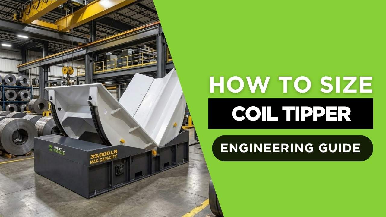
Engineering answer: size an industrial coil tipper or coil upender from the verified maximum load, coil geometry, center-of-gravity location, support contact, rotation path, duty cycle, loading method and required safety functions. Rated tonnage is only the starting point.
Use the MCT coil tipper and coil upender product page as the primary equipment reference. It covers standard 5-to-70-metric-ton models; the calculations below explain the application data required before a final machine is selected.
Primary Equipment Reference
MetalPress MCT machines rotate steel, aluminum and other industrial coils through a controlled 90-degree path. Review capacities, table sizes, controls and options on the product page, then submit the actual coil envelope and handling sequence for engineering review.
1. Define the Coil as an Engineering Load
A coil is not merely a number of tonnes. Its outside diameter, inside diameter, face width, winding density, banding, pallet or skid, eye orientation and contact surface determine how the load sits on the machine. Record the maximum and minimum values, not only the most common coil.
| Input | Symbol | Why it matters |
|---|---|---|
| Maximum coil mass | m | Establishes the static load and is used in force, torque and structural calculations. |
| Outside diameter | D | Controls the load envelope, cradle geometry, clearance and changing center-of-gravity height. |
| Inside diameter | d | Helps identify coil construction, lifting interfaces and the annular-volume estimate. |
| Coil face width | b | Affects support width, lateral stability, fork or crane handoff and contact pressure. |
| CG offset from rotation axis | e | Produces an overturning moment that the drive and structure must resist. |
| Cycles per hour and shifts | n | Defines thermal duty, bearing life, drive duty and maintenance expectations. |
| Loading and unloading method | — | Determines clearances, interlocks, supports and interfaces with cranes, forklifts or carts. |
2. Estimate Coil Mass from Geometry
If the verified coil weight is unavailable during early planning, a tightly wound homogeneous coil can be approximated as an annular cylinder. Use consistent SI units and the density specified for the actual material. Packaging, voids, telescoping, cores and mixed materials can make the real weight differ, so the measured or certified value governs final selection.
Annular coil volume
V = (π / 4) × (D² − d²) × b
V is volume in cubic metres, D is outside diameter, d is inside diameter and b is coil face width, all in metres.
Estimated mass
m = ρ × V
m is mass in kilograms and ρ is the actual material density in kilograms per cubic metre.
Worked geometry example
Consider a tightly wound steel coil with D = 1.50 m, d = 0.50 m and b = 1.20 m. Using ρ = 7,850 kg/m³ for an early estimate:
Calculated volume
V = (π / 4) × (1.50² − 0.50²) × 1.20 = 1.885 m³
This is the geometric annular volume before allowances for imperfect packing, banding or other details.
Calculated mass
m = 7,850 × 1.885 ≈ 14,800 kg
The early estimate is approximately 14.8 metric tonnes. Final equipment selection must use the verified maximum gross load, including any pallet, cradle or fixture carried by the machine.
3. Calculate the Gravity Moment About the Rotation Axis
The required drive and structural capacity depend on the moment produced as gravity acts through the combined center of gravity. The critical position may occur partway through rotation, not necessarily at either endpoint. The machine designer evaluates the complete geometry and motion profile.
Static gravity moment
Mg = m × g × e
Mg is moment in newton-metres, m is total moving mass in kilograms, g is gravitational acceleration and e is the perpendicular distance in metres from the rotation axis to the combined center-of-gravity line of action.
For the 14,800 kg example with a 0.075 m perpendicular offset, the static moment is approximately 10.9 kN·m. That number is not a motor-sizing answer by itself: acceleration, deceleration, friction, efficiency, geometry, impact, stops, fixtures and the selected safety philosophy also matter.
4. Include Fixtures, Eccentricity and Dynamic Duty
The combined center of gravity must include the coil, pallet, saddle, removable fixture and every moving component supported by the drive. For multiple bodies, the center of gravity along one axis can be calculated with a mass-weighted average.
Combined center of gravity
x̄ = Σ(mixi) / Σmi
Each mi is a component mass and xi is its center-of-gravity coordinate from the same reference datum.
A design or service factor may be applied to calculated loads, but there is no universal factor appropriate to every machine. The required factor and load cases must be chosen by the responsible engineer using duty, shock, uncertainty, applicable standards and the manufacturer’s design method. Do not multiply by an arbitrary internet value and treat the result as a rated capacity.
5. Check Support Pressure and Coil Protection
Coil edge and surface damage can occur even when the gross tonnage is acceptable. Approximate average support pressure is the supported force divided by the effective contact area; real pressure is not uniform and may be much higher at edges or small contact points.
Average contact pressure
pavg = F / Acontact
F is the supported force in newtons and Acontact is the effective contact area in square metres. The saddle profile, liners, coil geometry and material condition control local pressure.
Identify whether painted, polished, coated or thin-gauge coils require replaceable non-marking liners, adjustable supports, edge protection or special saddles. Also document whether the coil is banded and whether the bands may carry any handling load.
6. Match the Machine to the Complete Handling Sequence
| Question | Engineering implication |
|---|---|
| Does the coil arrive eye-to-sky or eye-to-side? | Defines the starting support, required 90-degree path and receiving orientation. |
| Will loading use a crane, forklift or transfer cart? | Changes access, clearances, controls, detection and interlocked handoff requirements. |
| Where does the coil go next? | A decoiler, slitter, storage cradle or press line may require a specific elevation and orientation. |
| How often will the unit cycle? | Affects drive duty, thermal performance, controls, maintenance and throughput. |
| Can personnel enter the rotation envelope? | Drives the risk assessment and selection of guards, sensing, interlocks and operating modes. |
| Is the load family highly variable? | May require adjustable supports, recipes, detection or a custom machine rather than a single fixed setup. |
When the coil must also travel between storage and production, coordinate the upender with the MCC coil transfer cart and transport cradle. The broader coil handling applications hub maps equipment to steel service centers, stamping, coil processing and roll-forming workflows.
7. Coil Tipper RFQ Checklist
- Maximum and minimum gross load, including fixtures and pallets
- Outside diameter, inside diameter and face-width ranges
- Material, surface condition, banding and permitted contact areas
- Starting and final eye orientation
- Crane, forklift, cart or automated loading method
- Receiving equipment, elevation and positional tolerance
- Cycles per hour, shifts per day and required availability
- Electrical supply, controls, communication and plant standards
- Safeguarding concept, access needs and maintenance isolation
- Floor condition, anchoring, available envelope and installation constraints
Frequently Asked Questions
Is coil-tipper capacity determined only by tonnage?
No. Tonnage establishes the gross-load class, but geometry, center of gravity, support pressure, rotation path, duty cycle, handoff method and safeguarding determine whether a particular machine fits the application.
Can coil weight be calculated from outside and inside diameter?
It can be estimated for a homogeneous tightly wound coil using annular-cylinder volume and actual material density. Use the measured or certified maximum gross load for final equipment selection.
What is the most important center-of-gravity input?
The machine designer needs the combined center of gravity of the coil, fixtures and moving supports relative to the rotation axis throughout the motion. Eccentric loading changes torque and structural load.
Should I choose the next standard tonnage above my coil weight?
Not automatically. A nominal capacity comparison is only a preliminary screen. The manufacturer must review the full load envelope, duty and installation before confirming a model.
What information helps MetalPress quote a coil upender?
Provide verified load and dimensions, orientations, loading and unloading sequence, cycle rate, utilities, controls, safeguards, layout drawings and any applicable plant or regulatory requirements.
Make the Product Page the Commercial Destination
For MCT model capacities, options, videos and quotation information, continue to the MetalPress coil tipper and coil upender product page.
References and Engineering Resources
- MetalPress MCT Coil Tipper / Coil Upender
- ISO 12100:2010 — Safety of machinery, risk assessment and risk reduction
- OSHA 1910.212 — General requirements for all machines
- NIST Guide for the Use of the International System of Units (SI)
Engineering note: This article provides planning concepts, not a final machine design or site-specific safety determination. Actual equipment must be selected and validated from the complete load, duty cycle, installation, safeguarding, controls and applicable-code requirements.