
ANGLE IRON & FLAT BAR FABRICATION
Prepare angle and flat stock with suitable cuts, holes and notches, supported by consistent gauging and repeat positioning.
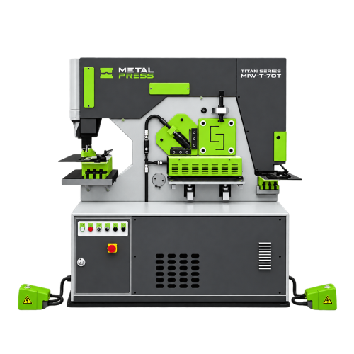
Equipment for Angle Iron & Flat Bar Fabrication
Angle iron and flat bar fabrication starts with preparing stock to the lengths, hole locations and end details required for the next operation. Supports, frames, braces and mounting components can need different combinations of shearing, punching and notching.
The MIW-T hydraulic ironworker brings dedicated workstations together for suitable stock preparation. Select the station and tooling around the actual section dimensions, material strength, thickness and finished geometry—not one headline machine capacity.
For finished connection-part planning, see bracket, gusset and mounting-plate fabrication. This page focuses on the angle and flat stock preparation workflow.
Match the Stock to the Workstation
Define angle leg sizes and thickness, or flat-bar width and thickness, together with cut length, hole pattern and notch geometry. Review access, support and positioning at each operation.
Shearing, Punching & Notching Angle and Flat Stock
Use the relevant ironworker station for the required stock section. Straight cuts, angle cuts and miter work must fit the specific blades, tooling and published station rating. Do not assume every model or attachment provides every cutting geometry.
For holes, specify diameter, material thickness and the reach required to position the workpiece. For notches, provide the profile and dimensions and check tool clearance around the angle legs or existing features. Review the MIW-T ironworker workstations and optional tooling against those requirements.
Plan support for long stock and define how the cut or punched part is located and removed at each station. Handling arrangements and repeat stops should suit the stock length and batch size.
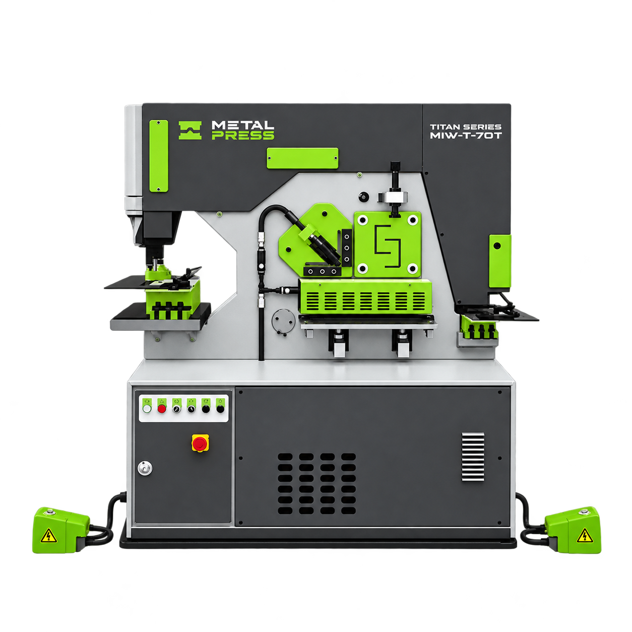
Plan Repeatable Stock Preparation
Cut length & reference ends
Choose a consistent datum end and define the finished length, cut angle and acceptable end condition. Account for any subsequent deburring or finishing in the drawing and inspection plan.
Hole location & access
Define hole centers from the specified reference edges. Check punch access, throat depth, angle-leg interference and workpiece support before selecting tooling. Hole size and material thickness must suit the station and tool combination.
Gauging & repeat positioning
Review stops, support tables and available gauging arrangements for recurring cut lengths and hole patterns. Specify whether repositioning is manual or requires an optional positioning system. Confirm the proposed configuration rather than assuming automation is standard.
Operation sequence & inspection
Decide whether cutting, punching or notching comes first based on access and the available reference surfaces. Check length, hole location, notch dimensions, burrs and fit-up at defined inspection points.
Material & Section-Specific Capacity
Provide the exact material grade and condition, not just “steel.” For angle stock, include both leg dimensions and thickness; for flat stock, include width and thickness. Material strength and section geometry affect the applicable machine rating and tooling selection.
Confirm the cutting and punching limits for each workstation separately. Where the drawing calls for special angles, shaped holes or unusual notches, review the actual tool arrangement and access before ordering. The finished assembly requires its own design and load assessment.
Prepare Your Angle & Flat Bar Enquiry
Send the stock specification, material grade, section dimensions, cut lengths, end angles, hole sizes and locations, notch drawings and tolerances. Include typical batch quantities, recurring sizes and the longest stock to be handled.
Add available floor space, stock-support requirements, loading arrangements and site power. Discuss your angle iron and flat bar fabrication requirements with MetalPress to review the MIW-T model, individual workstations and tooling.
Angle Iron & Flat Bar Fabrication Questions
A hydraulic ironworker can combine suitable stock shearing, punching and notching operations. Review the MIW-T ironworker by station capacity, tooling and access for the actual angle or flat section.
Yes, when the section size, thickness and material fit the selected angle-shearing station and blades. Confirm the required cut geometry and model-specific rating.
Miter capability depends on the workstation, blade arrangement, tooling and stock geometry. Provide the required angle and section dimensions for configuration review; do not assume every ironworker setup makes the same cuts.
Specify hole diameter, material thickness, hole centers, edge distances and both angle-leg dimensions. Check throat access, leg interference, punch-and-die compatibility and workpiece support.
Use appropriate stops, gauges and locating references, with support suited to the stock. Review available optional positioning equipment against batch size and required tolerances.
The MIW-T hydraulic ironworker product page lists models, workstation specifications and configuration information. Use those ratings with the stock and part drawing to select the equipment.
PLAN YOUR NEXT
Share your angle and flat-stock requirements to review shearing, punching, notching, gauging and tooling.