

Blog
Why a Perfect CAD Bend Becomes a Bad Part: The Science of Press Brake Springback

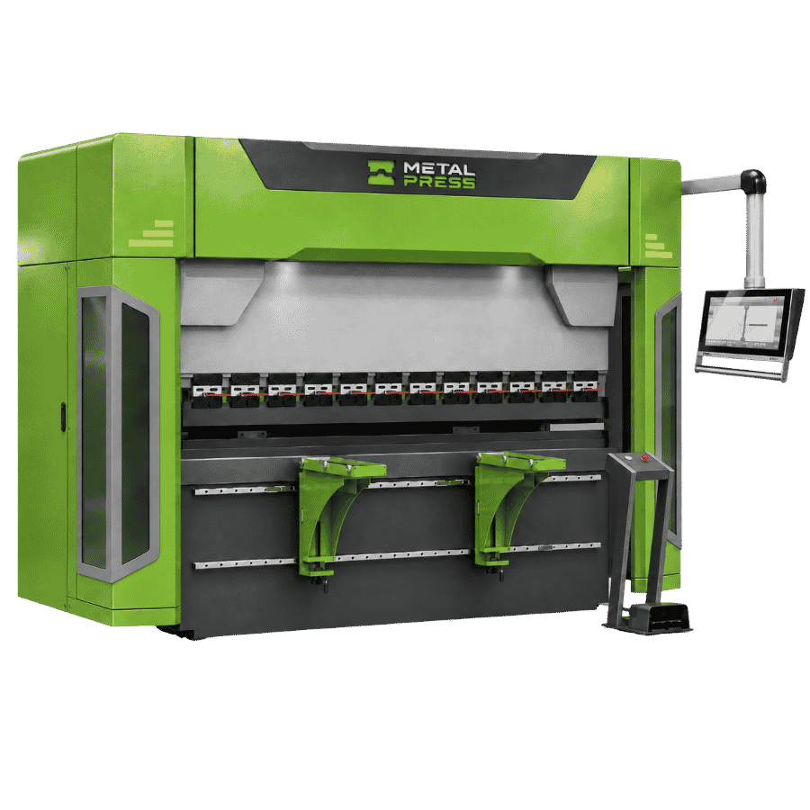
A bend can match its intended geometry under load and still miss the drawing after the tools release it. Press brake springback is the elastic recovery behind that change. The engineering task is to predict or measure the recovery, distinguish it from other errors, and validate the unloaded part. This briefing explains the physics, the limits of a springback calculation, and a practical way to build a repeatable compensation record. All numerical examples below are hypothetical calculations—not Titan test results or machine-setting instructions.
A fraction of a degree can become an assembly problem
Consider a rigid flange with an inspection point 100 mm from the bend axis. If its orientation differs from the nominal direction by 0.5°, the displacement normal to that nominal direction is approximately 0.87 mm. At a 250 mm lever arm, a 1° error gives approximately 4.36 mm. A small angular discrepancy can therefore matter greatly at a distant mounting hole or mating edge.
Geometric illustration: d = L sin(|δ|), where d is transverse displacement, L is the distance from an ideal fixed rotation axis, and δ is angular error. For 100 mm and 0.5°, d = 100 × sin(0.5°) ≈ 0.873 mm. This is one component of displacement, not the complete tolerance stack. Real parts also have bend-radius, flange-length, hole-location and datum errors.
This calculation does not diagnose springback. It explains why a bend-angle problem deserves more than a visual check against a square. The finished, unloaded geometry is what the assembly receives.
The same geometry matters in bracket and mounting-plate fabrication and enclosure and cabinet fabrication, where an angular deviation can move a mounting feature or mating edge away from its intended datum.
What actually happens when the punch unloads?
During bending, part of the deformation is recoverable and part is permanent. Once the material has yielded, plastic strain changes its shape; elastic strain remains superimposed on that plastic deformation. Removing the load changes the elastic strain distribution and the part adopts a new equilibrium shape. Residual stresses can remain—unloading does not mean that stress becomes zero everywhere.
For a simple V-bend, this recovery commonly opens the internal included angle and increases bend radius. More complicated forming histories can also produce curvature changes or twisting. WorldAutoSteel’s springback guidance explains the roles of strength, hardening and elastic response. Its stamping examples should not be treated as ready-made press-brake settings.
Angle convention is essential. In this article, α is the internal included angle: a flat sheet is 180° and a right-angle part is 90°. Define Δα = αfree − αloaded. Positive Δα means the bend opens after release. A controller or research paper may instead report bend rotation, 180° − α; the sign of the angular change then reverses. SSAB’s bending questions discusses elastic recovery and overbending; always translate the angle convention before comparing values.
A useful springback equation—and its boundary conditions
A beam idealization makes the mechanism easier to see. For a locally uniform section unloading elastically, the recovered curvature is approximated by Δκ = M/(EI), so κfree ≈ κloaded − M/(EI). Here M is the bending moment immediately before unloading, E is the relevant elastic unloading modulus, and I is the second moment of area. For a rectangular strip, I = bt³/12, with strip width b and thickness t. Use consistent units; N·mm divided by N/mm² × mm⁴ gives curvature in mm⁻¹.
This is an explanatory model, not an air-bending punch-depth calculator. A real V-bend has contact transitions, a nonuniform bending-moment field, plastic deformation and changing geometry. The equation assumes elastic unloading and omits reverse plasticity, detailed contact, anisotropic constitutive response and machine compliance. Width, plane-stress or plane-strain conditions also matter. It cannot establish a safe tool, die opening or machine load.
A practical sheet metal springback calculation needs an appropriate material law and forming model, not just a nominal grade name. Garcia-Romeu, Ciurana and Ferrer (2007) investigated air-bending springback experimentally across material, thickness and angle combinations. Aerens, Vorkov and Duflou (2019) specifically examined how variation in elastic modulus affects prediction. Their studies are a reason to test the assumptions—not a basis for copying a universal correction angle.
Which variables belong in the bending record?
| Input | Why it belongs in the record | What to retain |
|---|---|---|
| Material response | Strength, work hardening and unloading response influence recovery. | Grade, condition/temper, heat or coil identification and relevant material data. |
| Actual thickness | Changes geometry, stiffness and contact conditions. | Measurements at defined locations, not only nominal gauge. |
| Tool geometry | Punch radius, die opening and contact conditions affect the formed bend. | Tool IDs, radii, opening, clamping and approved load limits. |
| Rolling direction and blank condition | A controlled trial must identify orientation and incoming condition. | Orientation relative to the bend, blank location, edge condition and relevant prior forming. |
| Bending and inspection conditions | Changing the method or measurement changes what is being compared. | Air bending/bottoming/other approved method, support, sequence, inspection position and restraint state. |
These inputs should be treated as a coupled system. SSAB identifies material properties, thickness, punch and die geometry among the factors affecting the finished angle. Its grade-specific recommendations are not interchangeable with data for an unverified alloy. Tool selection must also respect the material supplier’s minimum-radius guidance and the tool system’s permitted loading. See our press-brake tooling and bending-methods guide for that separate selection task.
Changing a die opening to influence springback also changes other process demands. Do not narrow the opening or increase penetration simply to chase an angle without rechecking force, contact, flange support, radius and the approved operating envelope.
For material-specific application planning, see stainless-steel cutting and bending. Keep the actual grade and condition associated with the accepted setup rather than treating all stainless steels as one material.
Worked example: estimate a local correction from two trial results
Hypothetical data, for calculation only: assume an approved trial system can determine an equivalent loaded included angle and an unloaded angle using a validated method. The material lot, thickness, tooling, bend length and measuring procedure remain fixed. The numbers below are invented teaching values, not measured MetalPress results.
| Trial | Loaded included angle, αL | Free included angle, αF | Observed opening, Δα |
|---|---|---|---|
| A | 87.0° | 91.4° | 4.4° |
| B | 85.5° | 89.8° | 4.3° |
The local slope is s = (89.8 − 91.4)/(85.5 − 87.0) = 1.067 degrees of free-angle change per degree of loaded-angle change. A linear interpolation for a 90.0° free angle gives αL,target = 87.0 + (90.0 − 91.4)/1.067 ≈ 85.69°. The estimate lies between the two trial conditions, rather than extrapolating beyond them.
The result is a candidate physical loaded angle under the assumptions—not a CNC entry or ram-position command. Machine coordinates, controller angle conventions, tooling and the control strategy determine how an approved correction is implemented. Do not insert a measuring instrument into a loaded tool space; obtain any in-process value only through a supplier-approved measurement system and procedure.
Produce a confirmation part and inspect it unloaded. If repeated parts scatter substantially, correcting the mean alone will not solve the problem. Investigate incoming material, setup, locating and measurement variation. The two hypothetical observations illustrate interpolation; they establish neither linearity over a wider range nor production capability.
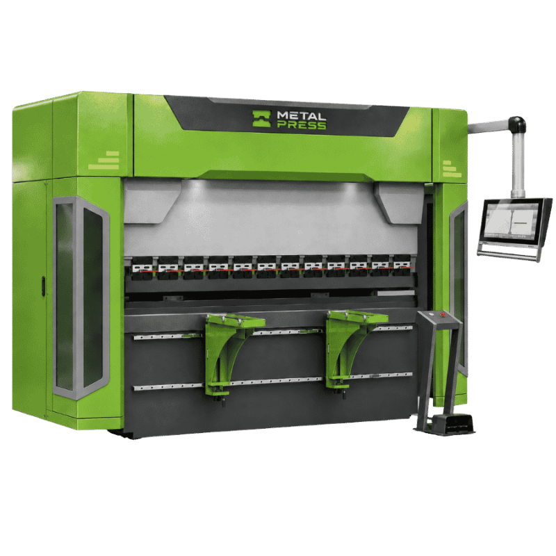
Titan Servo-Hydraulic CNC Press Brake
Review models, bending lengths, tooling and quotation inputs for your parts.
Separate springback from the other sources of bend error
| Observed pattern | Candidate causes to investigate | Useful comparison |
|---|---|---|
| The bend changes between loaded and free states. | Material elastic recovery, alongside any measurement or restraint difference. | Comparable loaded/free observations using an approved method. |
| The center angle differs from the ends on a long bend. | Machine/tool deflection, crowning setup, alignment, support or local material variation. | Measure defined positions along the same bend. |
| Angle is acceptable but a flange or hole misses its datum. | Blank geometry, bend allowance, locating reference, bend sequence or accumulated error. | Inspect the blank and dimensional datum scheme separately from angle. |
| Parts vary despite an unchanged program. | Material/thickness differences, seating, tooling condition, locating or inspection repeatability. | Repeat a controlled setup and retain material identity. |
These patterns are clues, not unique diagnoses, and several causes may coexist. SSAB distinguishes material springback from machine deflection and crowning. A spatially varying angle error is not automatically cured by a uniform overbend correction. Our crowning and bend-angle consistency article covers that separate issue; this article focuses on material recovery and its validation.
Bend allowance addresses the developed length through the bend. A K-factor used for flat-pattern development is not, by itself, a springback compensation model. Verify flat-pattern dimensions and unloaded bend angle as separate characteristics.
For multi-bend sheet-metal parts, inspect the intermediate geometry and datum changes as well as the final part. A later bend or locating step can introduce a dimensional error even when one earlier angle was accepted.
Build a repeatable verification procedure
The following is a proposed documentation framework, not a substitute for the machine manual, risk assessment or an approved operating procedure. Set the acceptance method before modifying the setup.
- Define the drawing characteristic: included angle or bend rotation, tolerance, datum references and whether the part is inspected free or restrained.
- Record the material identity, actual thickness, orientation, blank condition, tool IDs, approved setup and program revision.
- Verify the measuring method, instrument suitability and consistent seating. Identify where along the bend each reading is taken.
- Make representative confirmation parts through the approved process. Use the same unloaded inspection condition and record the elapsed measurement interval where it is relevant.
- Repeat measurements and parts sufficiently to distinguish measurement variation from process variation. Define sample size and capability criteria in the quality plan; a successful first part is not a capability study.
- Save both the accepted result and its limits of applicability. Revalidate when material condition, tooling, geometry, sequence or relevant machine setup changes.
Measurement uncertainty matters when the acceptance band is narrow. For the hypothetical relation Δα = αF − αL, two independent angle measurements with standard uncertainties of 0.10° each give u(Δα) = √(0.10² + 0.10²) ≈ 0.14°. This is a standard uncertainty, not automatically an expanded uncertainty or a tolerance. Correlated measurements and different instruments require a different uncertainty model. The example is an original calculation, not a claimed instrument specification. NIST explains the propagation of combined standard uncertainty.
What simulation and CNC control can—and cannot—establish
Simulation is most useful when its material response and contact assumptions match the forming case and its output is checked against representative parts. Šarić, Mehmedović and Butković compared finite-element predictions with air-bending experiments using aluminum, mild steel and higher-strength steel; their model significantly underestimated springback for the higher-strength material. Their 2016 study illustrates why agreement for one material does not validate a model for another.
Özdemir’s DP600 air-V-bending study used a designed experiment involving punch radii and sheet thicknesses. That 2020 work demonstrates a structured way to study parameter effects, but its fitted response should not be transferred to different tooling or materials as a universal equation.
For equipment selection, distinguish programmed compensation, in-process angle measurement, automatic correction and crowning. They address different parts of the problem. Ask which functions are actually included, which require options, what is measured, when correction occurs and how the finished part is verified. A repeatable axis position alone is not proof of a repeatable unloaded angle across changing material lots.
For a specific job, use the Titan servo-hydraulic CNC press-brake product page for the commercial configuration discussion. Provide the drawing, material range, tooling proposal, bend length and tolerance. Obtain written confirmation of the ordered control and measurement functions. No automatic angle-sensing feature or springback accuracy is attributed to the Titan by this article.
Capacity and working envelope remain separate selection checks. Use our press-brake tonnage, bending-length and backgauge guide for those requirements; an angle-compensation calculation does not establish machine or tooling capacity.
Frequently Asked Questions
What is springback in press-brake bending?
It is the change in geometry as the material elastically recovers after unloading. For a simple V-bend it commonly opens the internal included angle. Always specify the angle convention and the measurement restraint state.
Is there one spring back calculation formula for every sheet metal part?
No single correction angle or simplified formula is valid for every material, bend geometry and tooling arrangement. Use a suitable model for estimation and representative unloaded-part measurements for validation.
Does a larger press brake eliminate springback?
A higher machine force rating does not remove the material’s elastic recovery. Capacity, approved tooling, control functions and compensation must be evaluated separately.
Can crowning correct springback?
Crowning compensates for relevant machine/tool deflection along the bending length. It is not a universal substitute for material-specific angle compensation. Diagnose both spatial variation and unloaded angle.
Should I change the K-factor to fix a wrong bend angle?
Treat flat-pattern length and unloaded angle as separate characteristics. A K-factor used for bend allowance does not by itself predict material recovery after unloading.
References and scope of the evidence
- WorldAutoSteel, AHSS Application Guidelines: Springback. Industry guidance; stamping examples require context when applied to press braking.
- SSAB, 20 Questions About Bending. Manufacturer explanation of recovery, angle variables and minimum-radius considerations; grade-specific recommendations are limited to its products.
- SSAB, Press Bending. Manufacturer explanation distinguishing springback from deflection/crowning.
- Garcia-Romeu, M. L.; Ciurana, J.; Ferrer, I. (2007). Springback determination of sheet metals in an air bending process based on an experimental work. Journal of Materials Processing Technology, 191, 174–177. DOI: 10.1016/j.jmatprotec.2007.03.019. Publisher abstract and preview consulted; no unverified full-paper results quoted.
- Aerens, R.; Vorkov, V.; Duflou, J. R. (2019). Springback prediction and elasticity modulus variation. Procedia Manufacturing, 29, 185–192. DOI: 10.1016/j.promfg.2019.02.125. Publisher abstract consulted.
- Šarić, E.; Mehmedović, M.; Butković, S. (2016). Analysis of springback in air bending process. Journal for Technology of Plasticity, 41(2). Research abstract consulted; qualitative model-validation finding only.
- Özdemir, M. (2020). Optimization of Spring Back in Air V Bending Processing using Taguchi and RSM Method. Mechanics, 26(1). DOI: 10.5755/j01.mech.26.1.22831. Research abstract consulted; no fitted coefficients transferred.
- NIST, Combining Uncertainty Components. Primary metrology guidance for the independent-input uncertainty example; no instrument specification is implied.